Installation
Setup your development environment
Click on the corresponding image to display how to setup.

Arduino IDE
or

PlatformIO
Tip: The platformIO environment is the easiest to setup, because you do not need to setup the esp core neither the libraries by yourself.
Connect your board
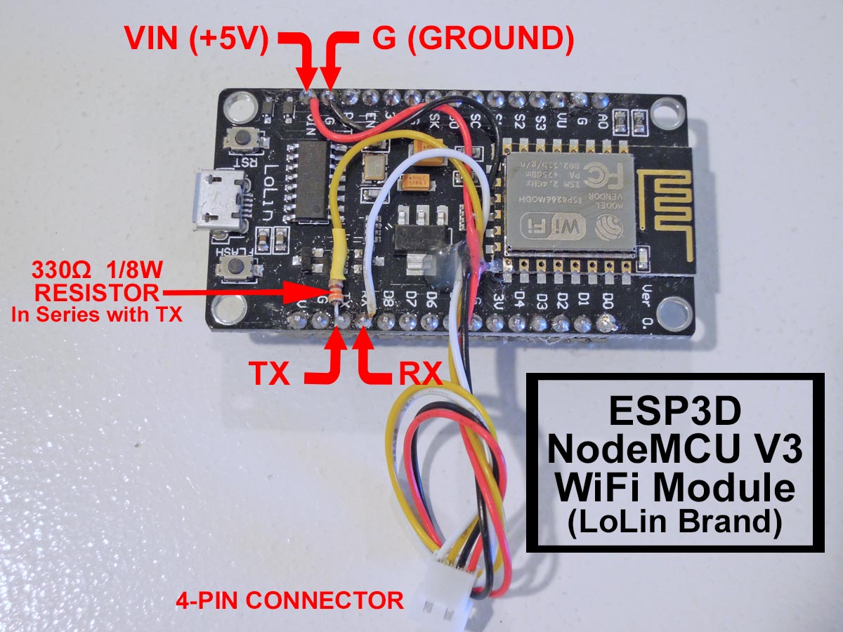
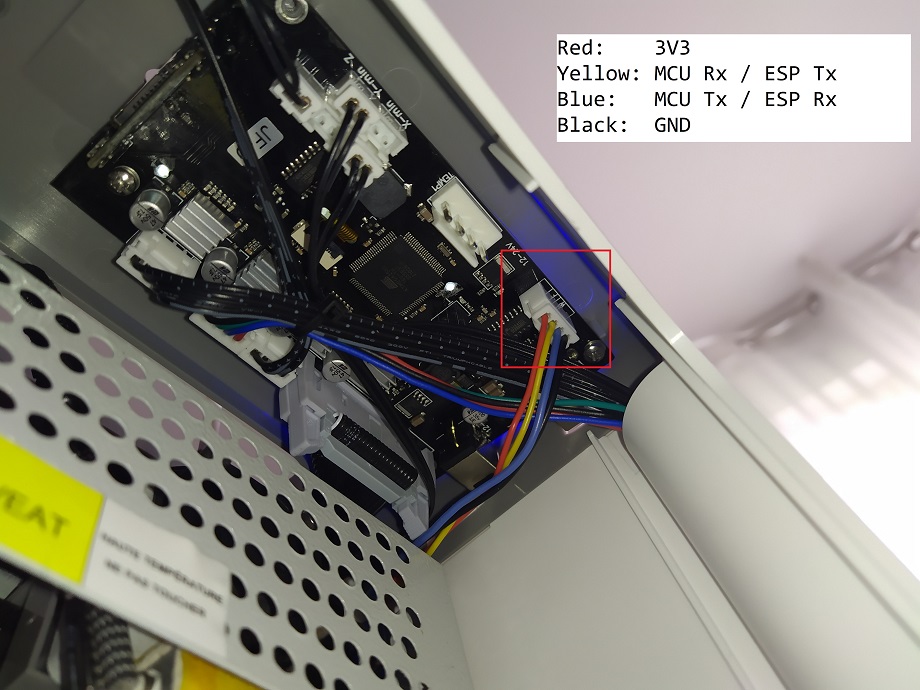
Connection between ESP and printer board needs 4 wires:
- ESP Tx needs to connect to Rx on MCU of printer board.
- ESP Rx needs to connect to Tx on MCU of printer board.
- You also need to power supply ESP board with with GND and 3V3 or 5V.
Connecting ESP board to target board
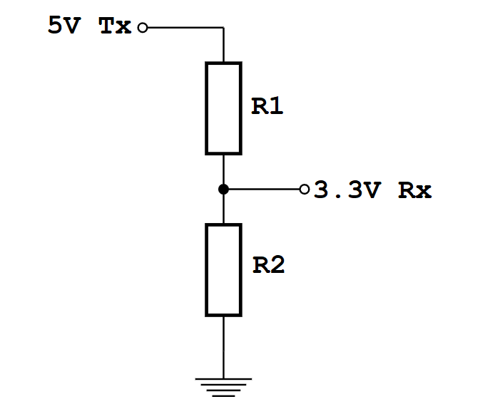
Be aware that ESP MCU is 3.3V on GPIO pin and some target board can be 3.3V and others 5V, so you may not be able to directly connect ESP board to target board.
Disclaimer : this wiki is for reference - you are responsible of your board supporting or not 5V, we are not responsible for any damage of wrong wiring.
ESP32 and ESP8266 MCU are only supporting 3.3V. Power supply them with 5V will likelly fry them immediatelly. As MCU is supplied at 3.3V, Tx and Rx signals will be at 3.3V even when board is supplied with 5V. Wether Rx pin is supporting 5V is controversial so we will keep on the safe side and only take datahseet as reference. It’s not recommended to have any signal (including Rx) be higher than power supply (3.3V here).
There are several points to take care. One should check that
- MCU1 Tx voltage is lower than MCU2 supply voltage
- Voh_min of Tx is higher than Vih_min of Rx (to check both ways)
- Vol_max of Tx is lower than Vil_max of Rx (to check both ways)
1 is mandatory and resistor voltage divider bridge or level shiffter is recommended
2 & 3 are not destructive there is just a slight risk signals are not read correctly. But it will work in most case as the limit values given by datasheets are rarelly met in mild conditions (using near 25°C and low current flowing from Tx to Rx)
For the divider bridge a value of R1=1k and R2=2.2k will be fine.
You could also use 10k and 22k or anything near a factor 2.
Connection diagrams for some printers and ESP boards
Printer motherboards
Anet boards up to v1.5
You will also have to unsolder the resistors R52 and R53 – they are zero ohm resistors, and serve no other purpose than connecting the atmega chip directly to the onboard USB to UART converter (the CH340 chip). Do it VERY careful – you don’t want to damage your board. If you don’t feel confident – don’t do it.
Now prepare the printer’s motherboard. It requires a simple modification, that does not interfere with it’s operation afterwards – just solder 3 pin x 2 row male header on J8, and add 2 jumpers (or jumper wires) as shown on the picture:
Connect the ESP to J3 repsecting pinout
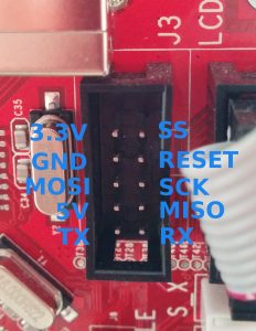
| ESP |
J3 |
| Tx |
Rx |
| Rx |
Tx |
| GND |
GND |
| VCC |
3.3V |
| CH_PD |
3.3V |
For more Info check lokster | space
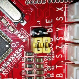
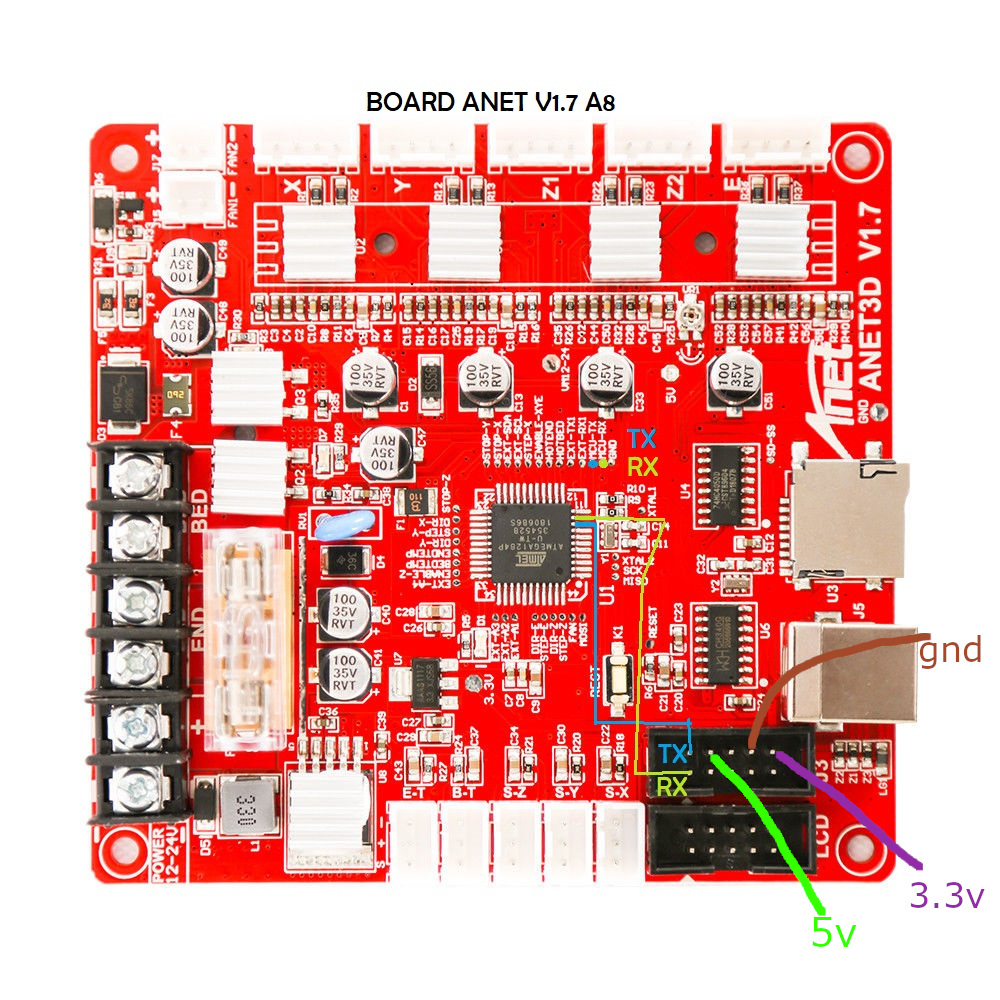
For connecting version 1.7 Anet boards
Unlike older boards this board does not require you to remove any resistors.
You will have to solder two wires from number 9 and number 10 its recommender to connect these to pin 1 and 2 of J3 connector.
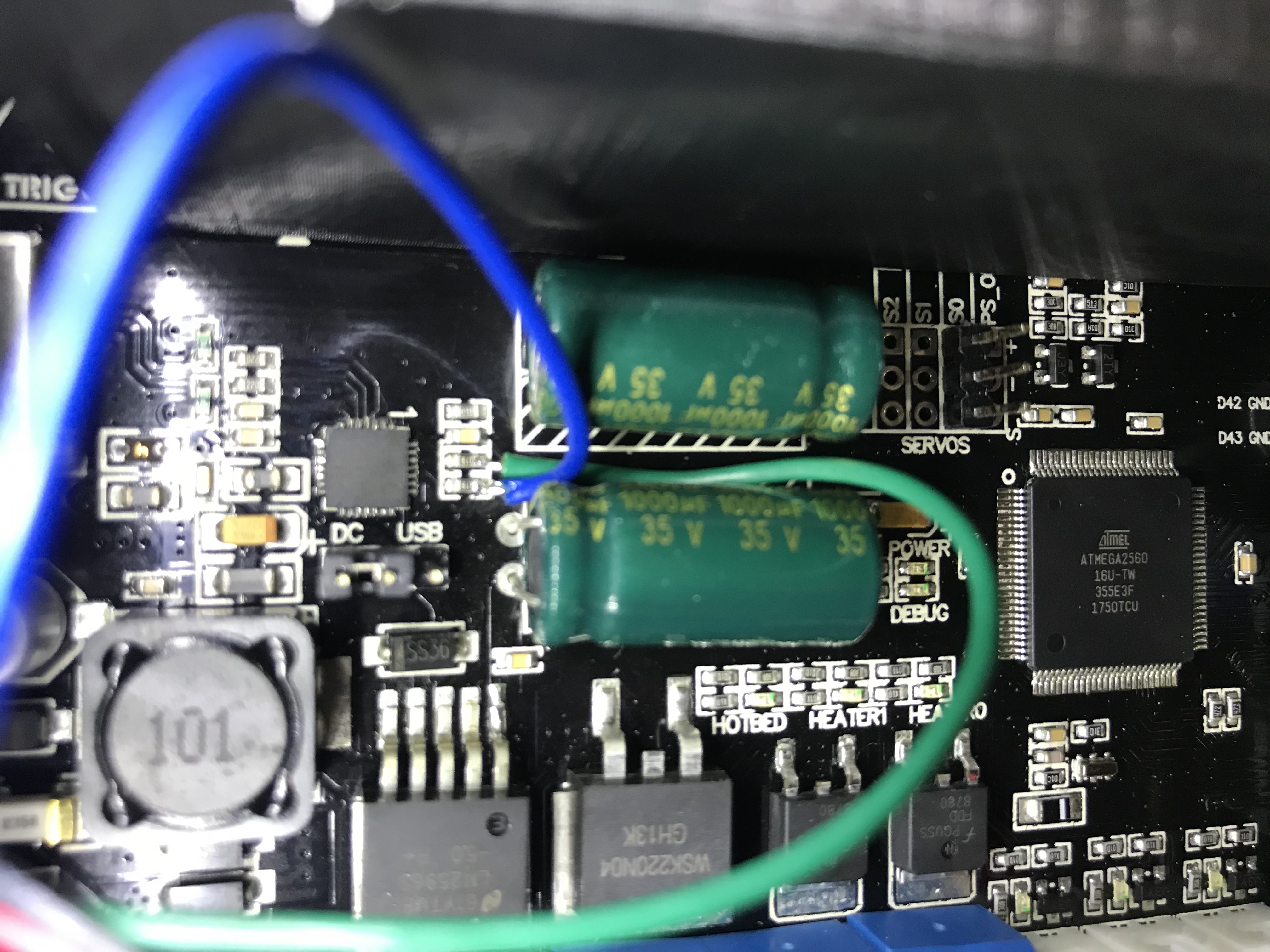
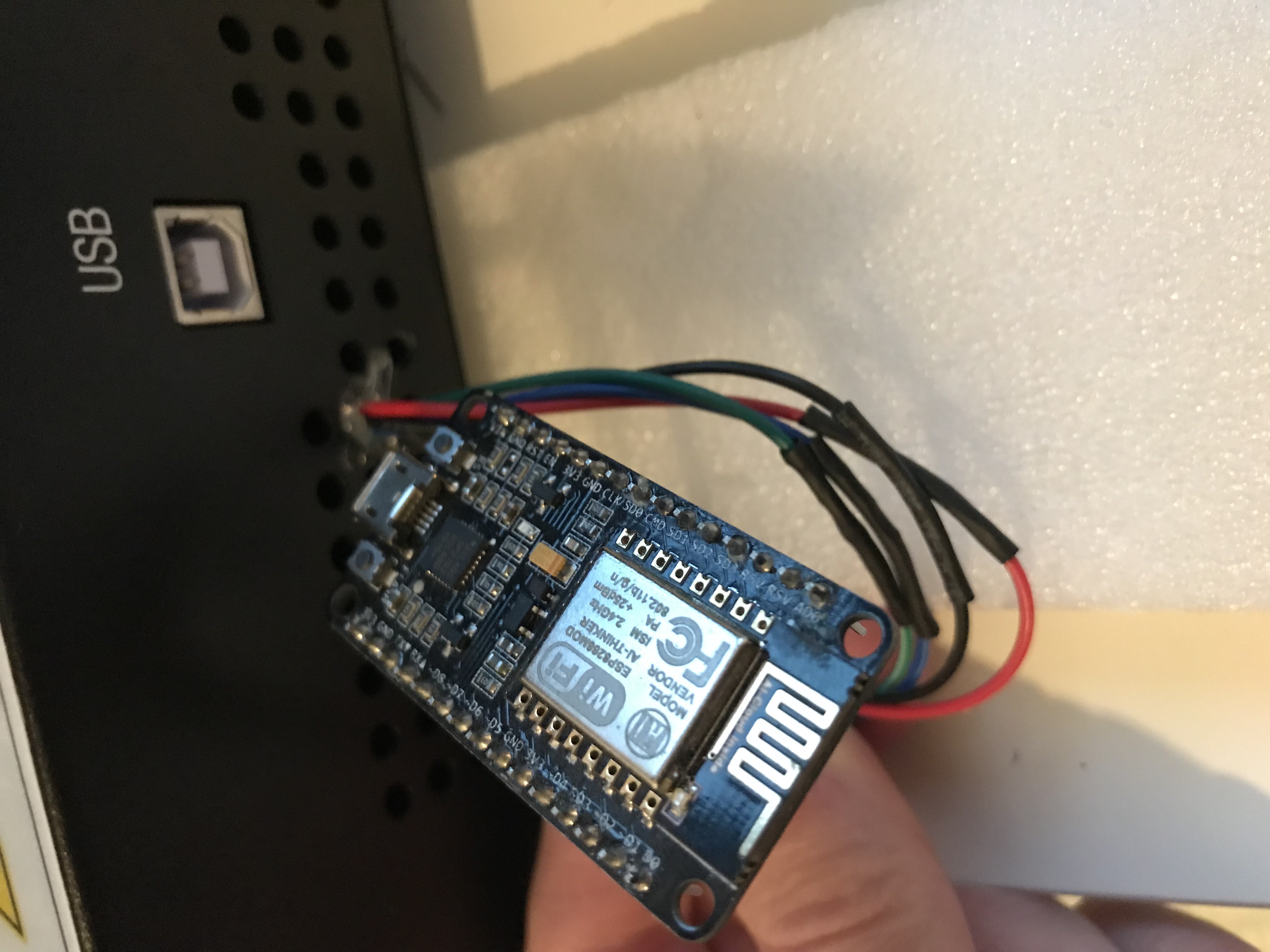
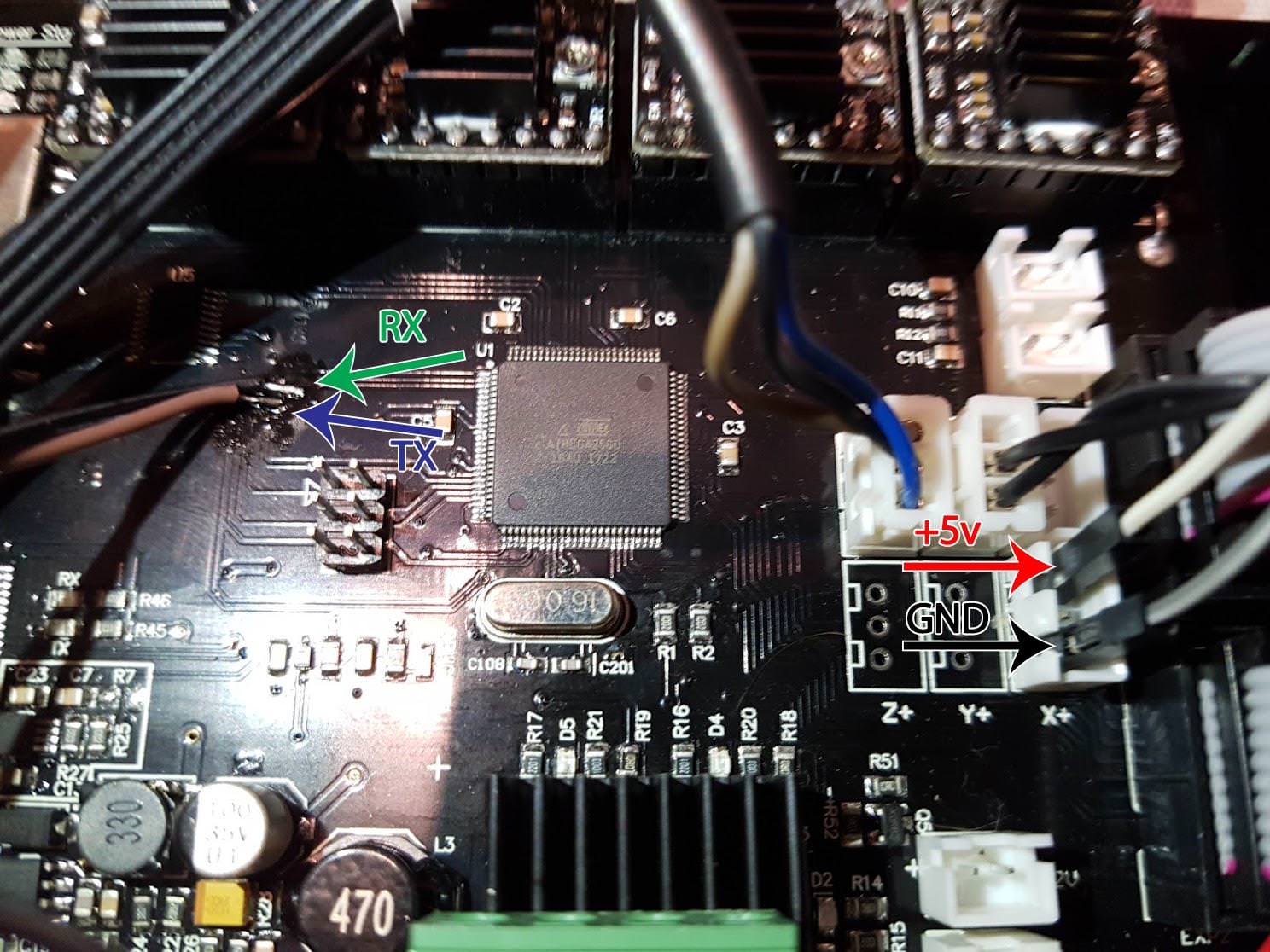
Anycubic i3 mega - Trigorilla 8bit board
To connect the ESP12e to the UART0. (Credits:197-murdock).
(Green = RX, Blue = TX)
5V (buck to 3.3v if directly connect to ESP - most development ESP boards already have this voltage limited built-in - but check!) and GND can be taken from the AUX3 exposed connector.
UART0 is normally used by USB port so don’t use both together - so this hack piggybacks on that same port at UART level.
AZSMZ LCD board
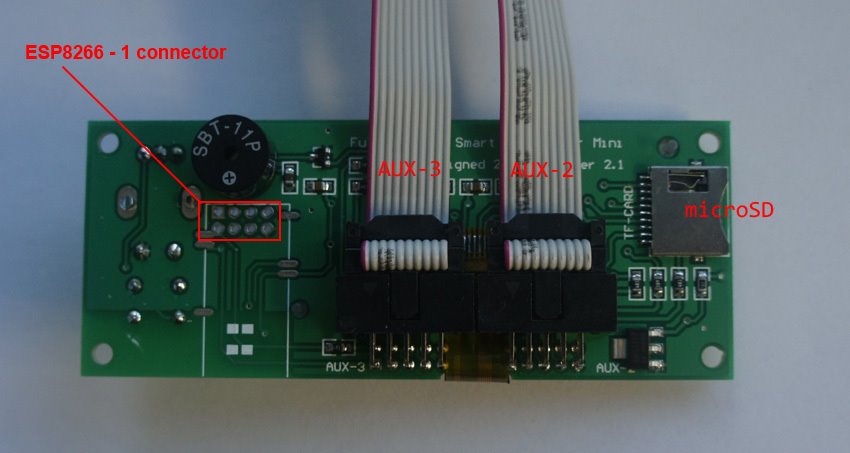
AZSMZ-mini board
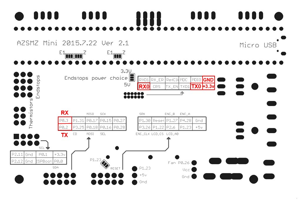
If you don’t have the soldering skills to grab the connectors from the unpopulated ethernet connection, you can also get 3.3v and GND from the ISP header (bottom left on the diagram above).
Azteeg X5 mini board

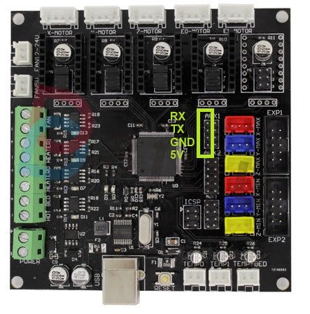
BIQU KFB2.0 board
all in one Ramps1.4/Mega2560 R3 controller based
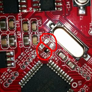
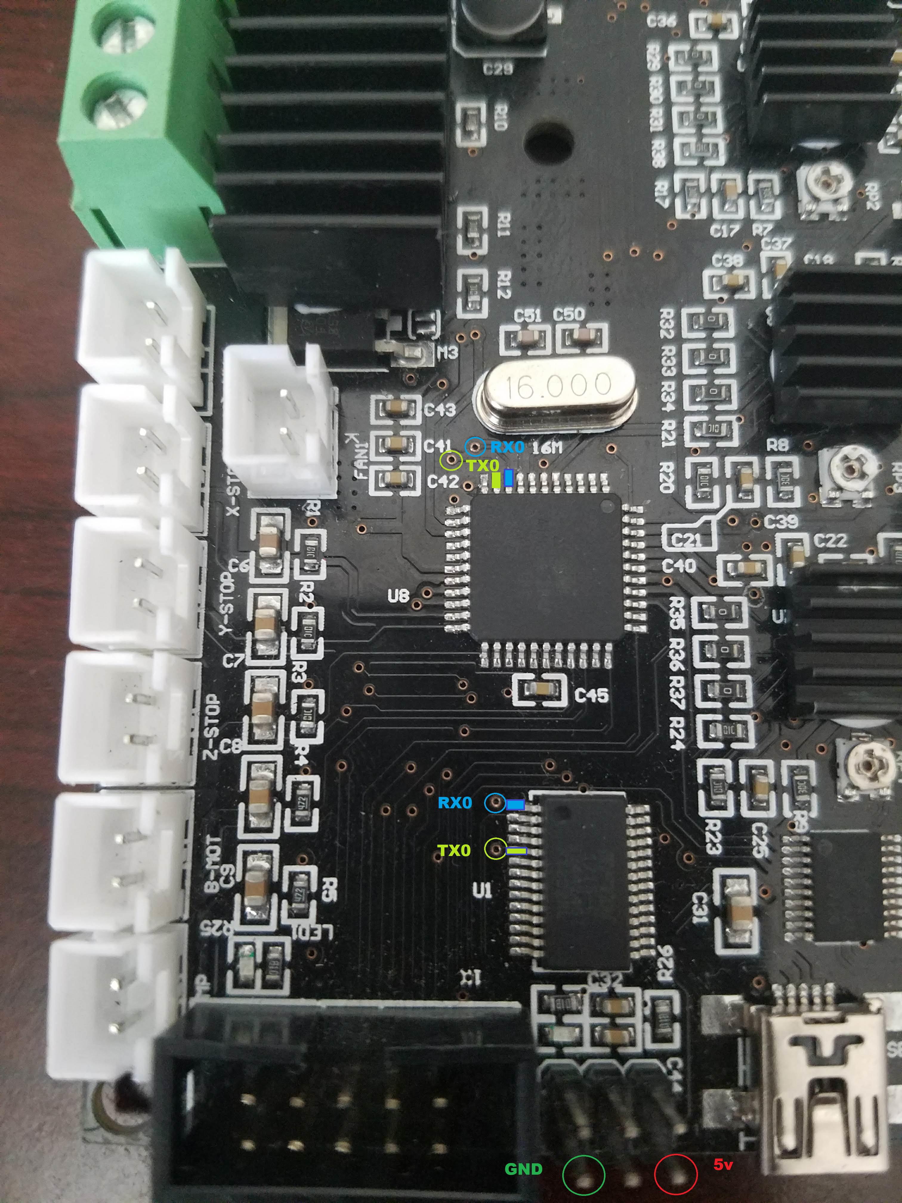
Creality CR10 Ender 3 board
For the Sanguino based CR-10 and Ender printers you will need to solder to any of the via circled (can also be done in the backside of board), or to the legs of the Arduino or ftdi. Connect TX from the board to RX of Wemos D1 mini and RX from board to TX of Wemos D1 mini. 5v and GND are located in the six pin header next to the LCD connector.
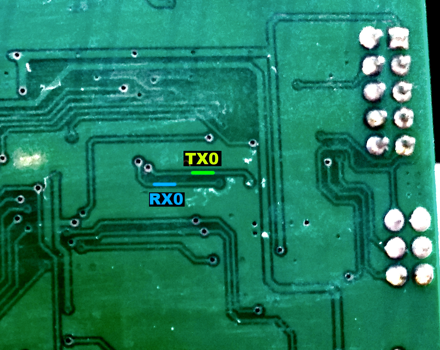
Since soldering might be difficult because the solder points are so close to each other, another option is to scrape off the insulation from the traces on the backside and solder there. Be extra careful not to scrape the surrounding ground plane. You need suitable fine scraping tools for this. The picture below shows an Ender-2 PCB.
Creality Ender 4 board
You will need to solder to small circle, or to the legs of the ATmega2560 (RXD0 pin 2, TXD0 pin 3)
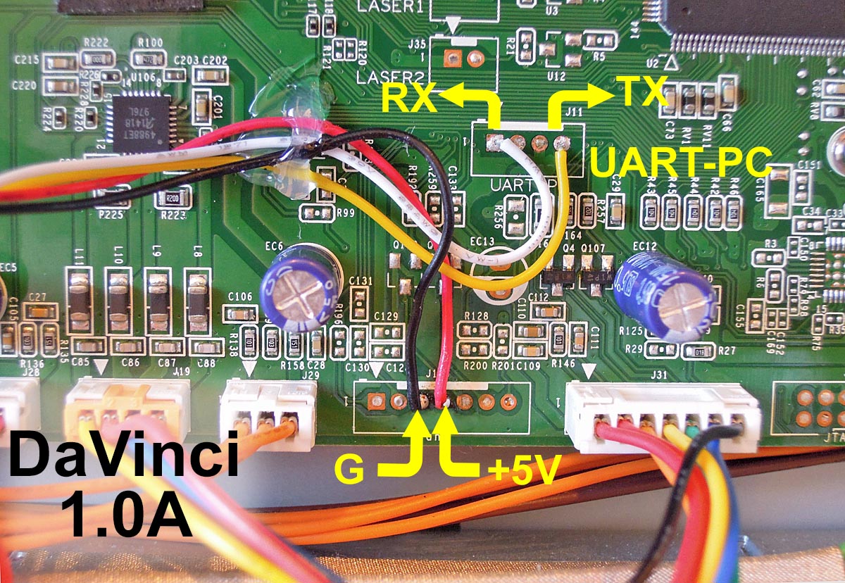
Davinci 1.0/2.0 board
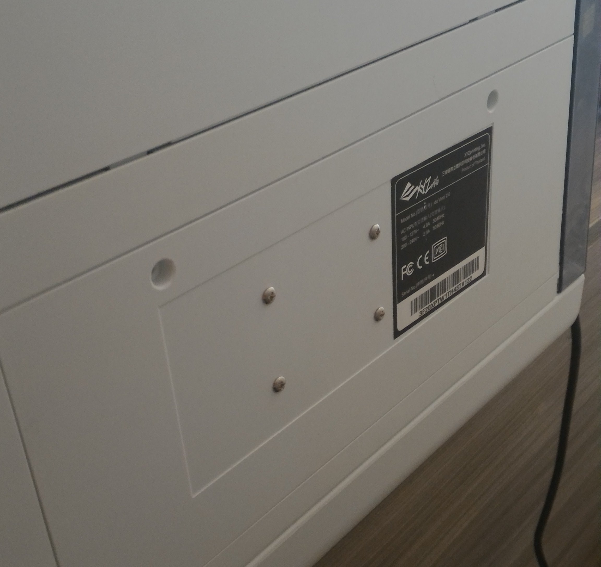
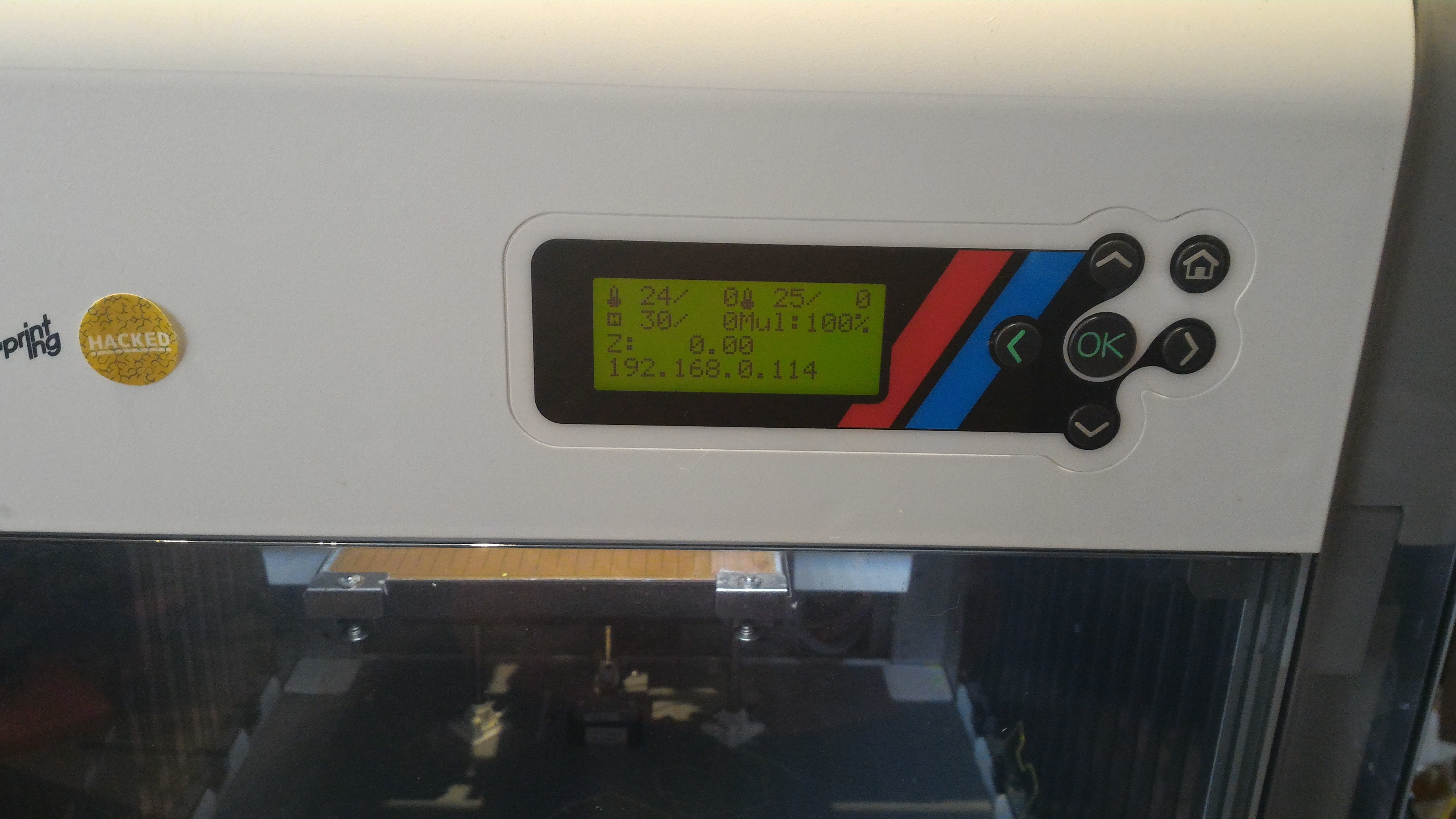
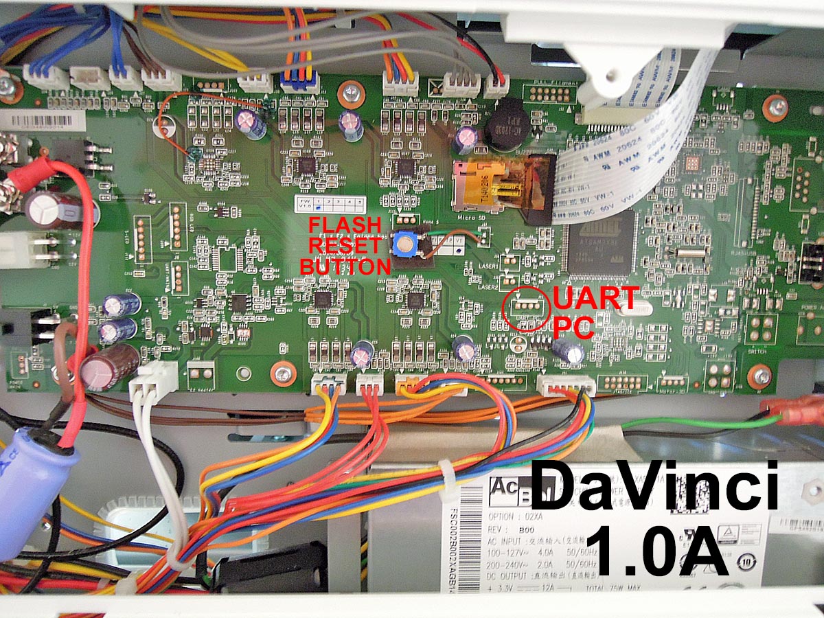
Davinci 1.0A board
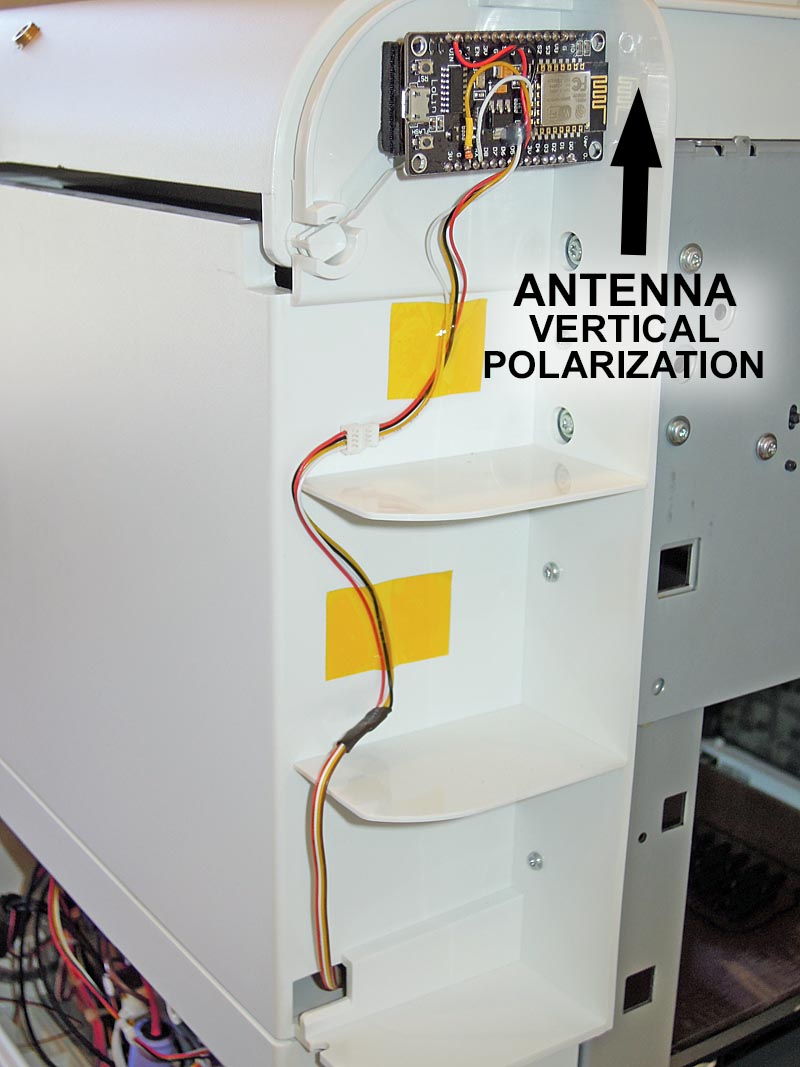
Alternate Module placement for increased WiFi range (outside metal chassis, antenna has vertical polarization)
MKS boards
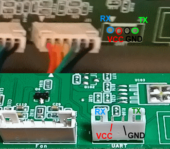
To connect the ESP3D to the MKS GEN v1.2 (but the v1.3 and above 1.4 is the most used today).
An ESP12E with the standard schematics, the two resistor connected to the RX pin are substituted by a 1N4148 diode, like in the Adafruit Huzzah board.
ESP12E is connected to the AUX1
ESP12E RX is connected to the pin NEAR GND of the upper row (Marked TXD on pinout.)
ESP12E TX is connected to the adiacent pin at the end of the upper row (Marked RXD on pinout.)
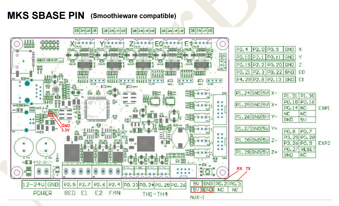
MKS Smoothieware board
RADDS board
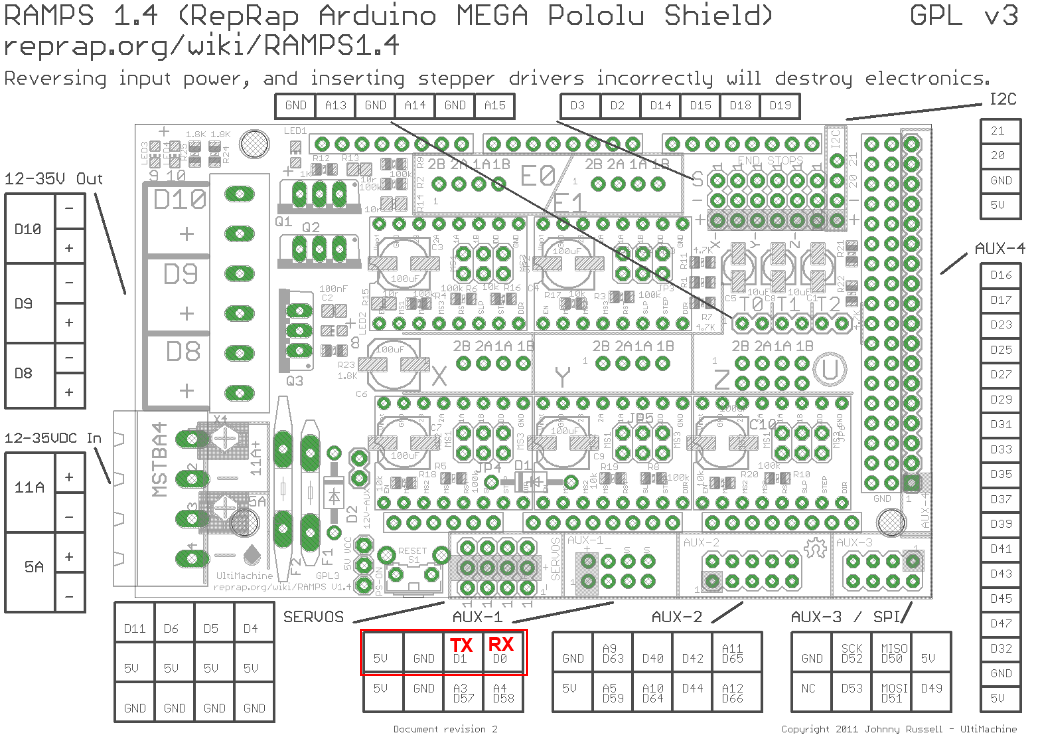
RAMPS 1.4/Re-ARM board
Ramps 1.4 can be used on Arduino Mega (repetier/marlin) and Re-ARM for ramps boards (smoothieware/marlin)
Alternative pins if use Re-ARM (J4/UART port)
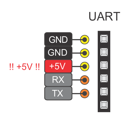
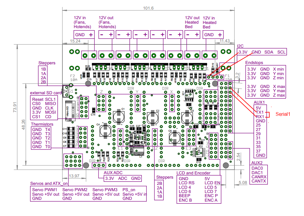
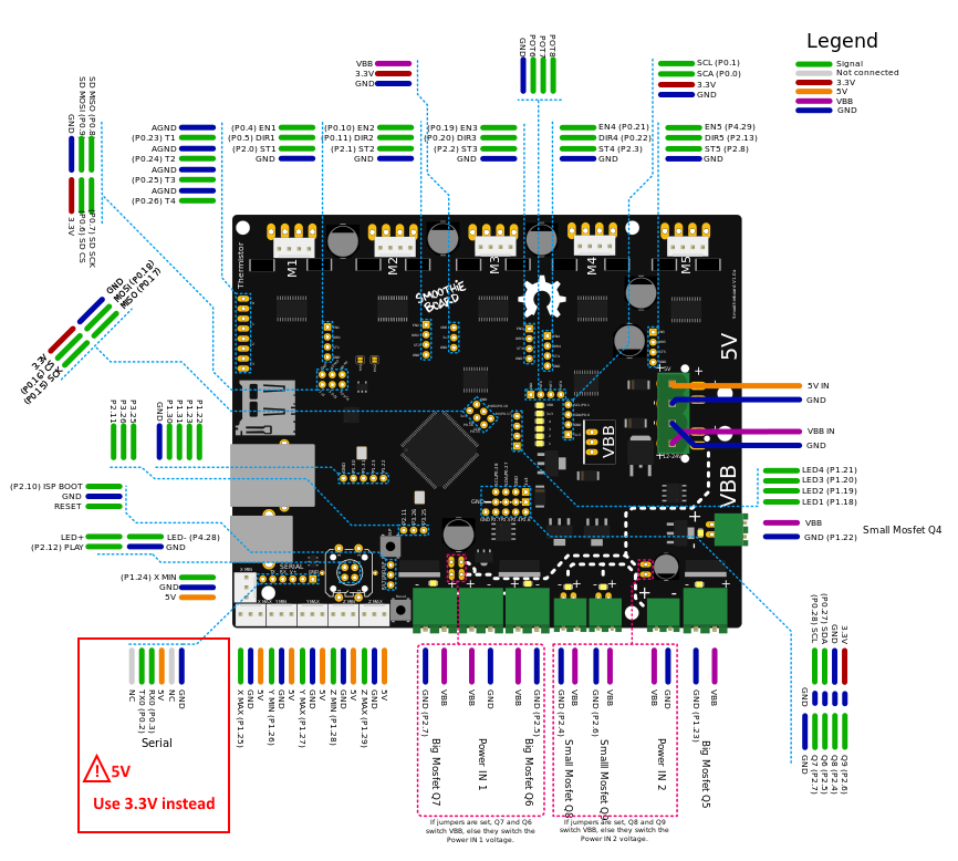
Smoothieboard board
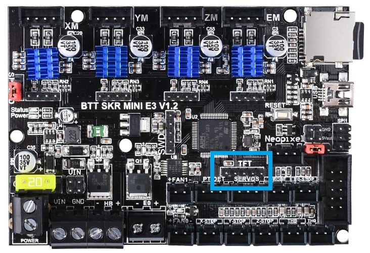
SKR Mini E3 board
This board is from Bigtreetech and went through various hardware revisions; all of them still feature a TFT pin header which is where you can tap the TX and RX needed. The wiring below is made with a 1.2 board, but the same applies for the other revisions as well; if you need the exact schematic for your mainboard version, you can check Bigtreetech’s github repository.
You literally cannot miss it because the TFT connector is labeled on the board; you can use dupont connectors for the wiring job, no soldering skills needed as long as your ESP comes with pre soldered headers.
Just a heads up: the TFT connector provides 5V DC, so be sure to provide them on the correct ESP pin and, most importantly, if your ESP can work with 5 volts as input. You should also pay attention on the board orientation in the schematic, although I oriented it the same way as the actual picture on the left so it’s easier for you.
Weedo Tina2 board
This printer is also brand labelled as Monoprice MP cadet 3D printer
In marlin this connection is serial port 3.
Note the Mega2560 is 5V powered and ESP is 3V3 powered.
For printer boards not listed here
Vast majority of printers have an USB port that is converted to UART before going to MCU. Many printers also have additional (unused) UART port you can use. When possible, always use the additional port for connecting ESP to printer board. When no additional UART port is available you might use the Tx and Rx lines between USB/UART converter and MCU but it’s recommended to cut (in a reversible way) the line to USB/UART converter to avoid conflicts.
If the board is ATmega based the simplest way to find a usable UART port for the ESP is to open ATmega datasheet.
ESP boards
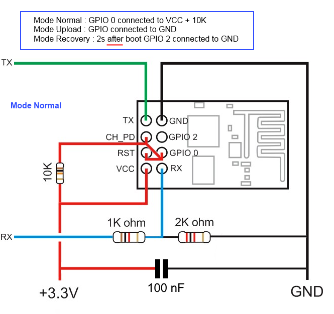
ESP-01
- Use GPIO2 to ground to reset all settings in hard way - 2-6 sec after boot / not before!! Set GPIO2 to ground before boot change boot mode and go to special boot that do not reach FW. Currently boot take 10 sec - giving 8 seconds to connect GPIO2 to GND and do an hard recovery for settings
- Use GPIO0 to ground to be in update mode
ESP-01 serial wifi module
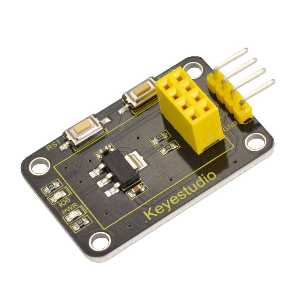
more info about the Breakout PCB: keyestudio
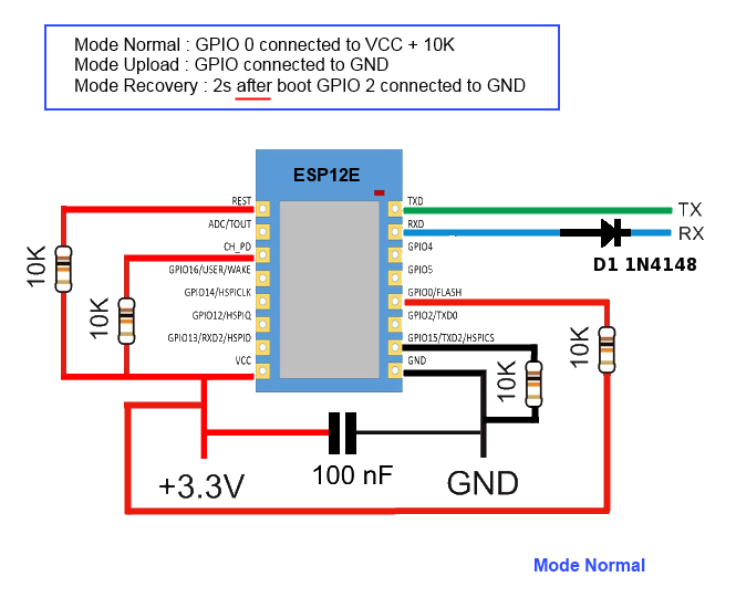
ESP-12E/F
ESP need 3.3v, it is not 5v tolerant, if printer board use more than 3.3V like 5V on ramps.
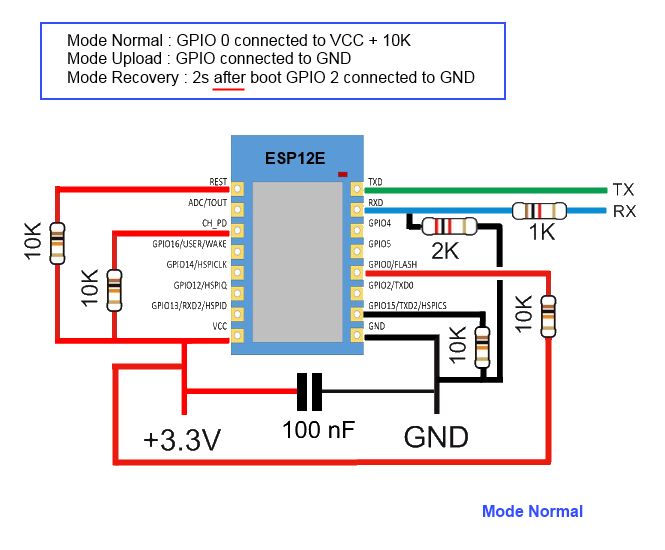
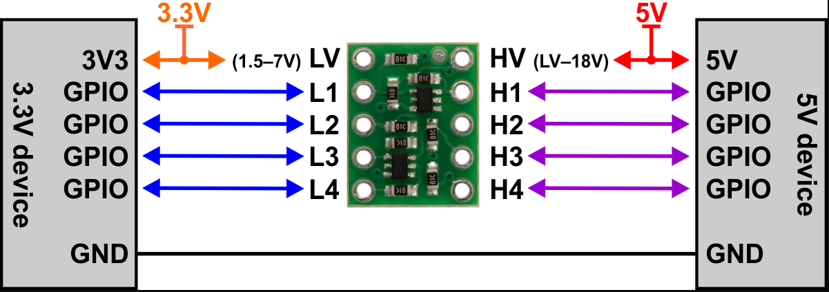
you can also use Logic LevelConverter Bi-Directional
In order to flash some ESP12E/F boards via their UART interface, the following pins need to be connected:
- VCC to GPIO2
- GND to GPIO0
This has been tested with ESP-12-E boards labeled “ESP8266 For ESP3D FYSETC.COM”
ESP 12F serial wifi module
ESP-12F based serial wifi module (eg from aliexpress ) contains built in 2-way levelshifter/bi-directional logic level converter. So it can be powered via 5V uart from the target’ motherboard.
- We need to manualy ground the
IO0 while powering up to start in flash mode while powering up (there is no switch for that, neither for reset)
- Use FTDI adapter as usb2serial
- Need to see in console/serial monitor boot mode is (1,7).
- baudrate: 74880
rst cause:2, boot mode:(3,7)
- Then flash like other esp based board for esp3d
ESP32-Cam
Note: 5V is power supply input and 3V3 is output from regulator. UART Tx and RX signals will be 3.3V
NodeMCU V2/V3
Sonoff
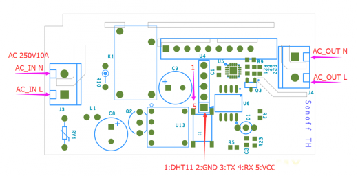
Relay is connected by GPIO12, it can be handled using ESP201 command:
*Get/Set pin value
[ESP201]P<pin> V<value> [PULLUP=YES RAW=YES]
if no V<value> get P<pin> value
if V<value> 0/1 set INPUT_PULLUP value, but for GPIO16 INPUT_PULLDOWN_16
GPIO1 and GPIO3 cannot be used as they are used for serial
if PULLUP=YES set input pull up, if not set input
if RAW=YES do not set pinmode just read value
So [ESP201]P12 V0 should be off and [ESP201]P12 V1 should be on
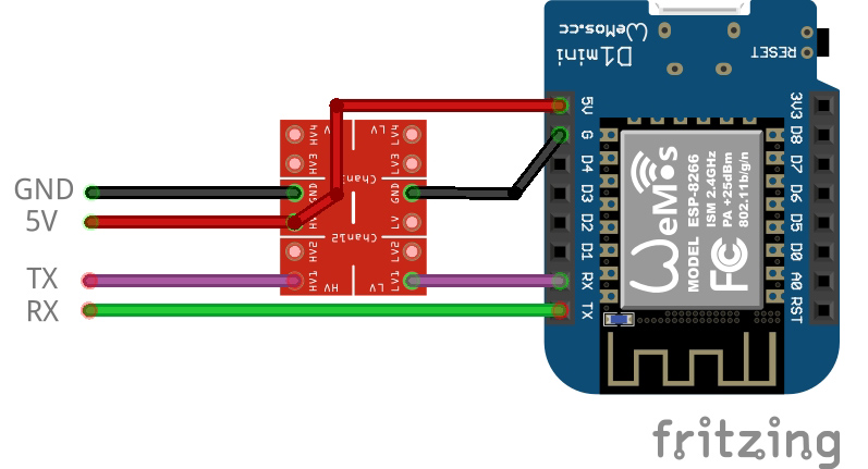
Wemos D1 mini
Connection with logic level conveter:
example:
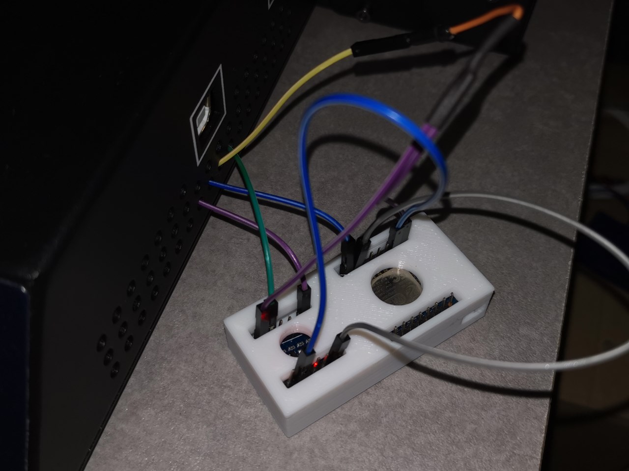
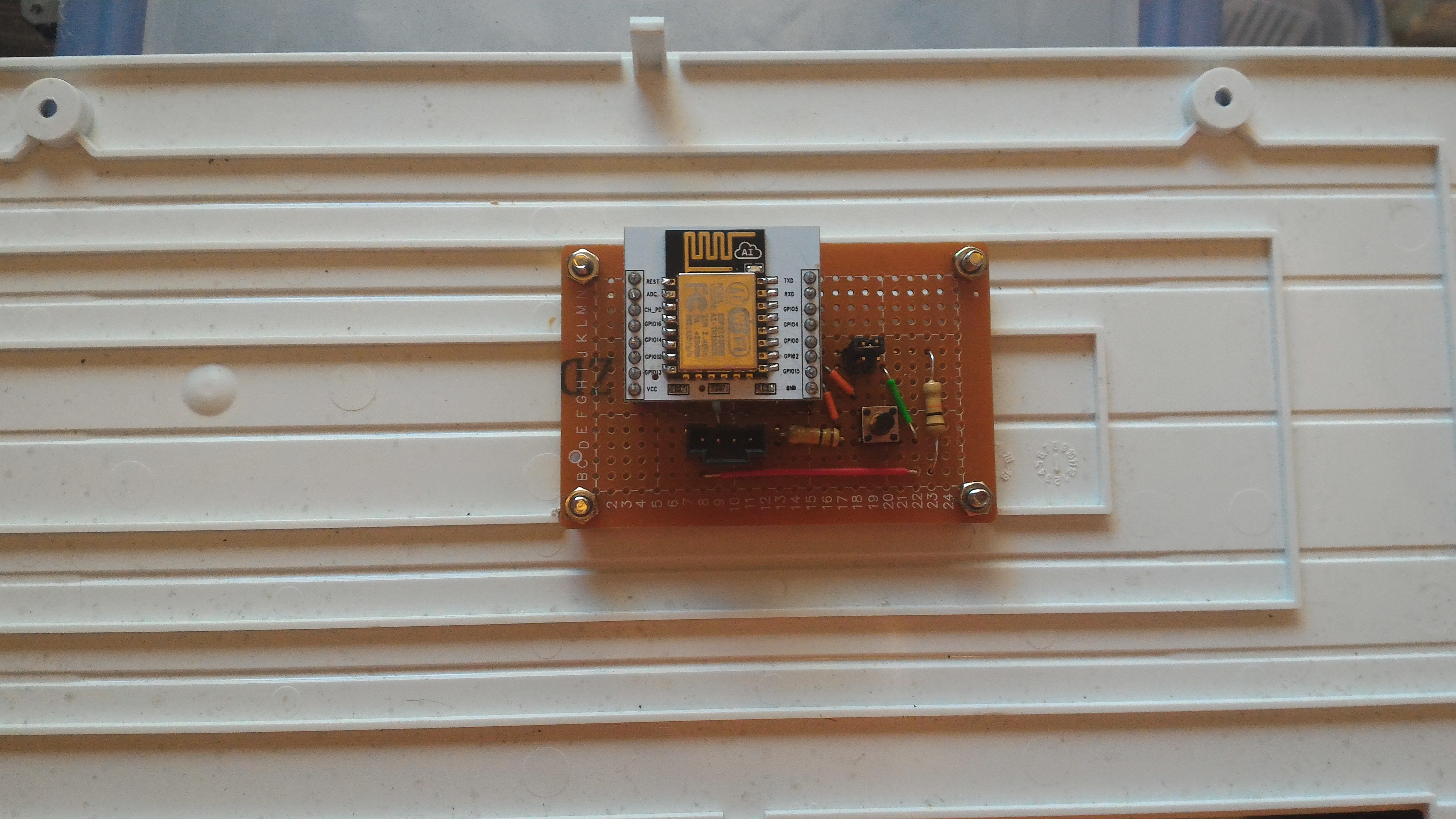
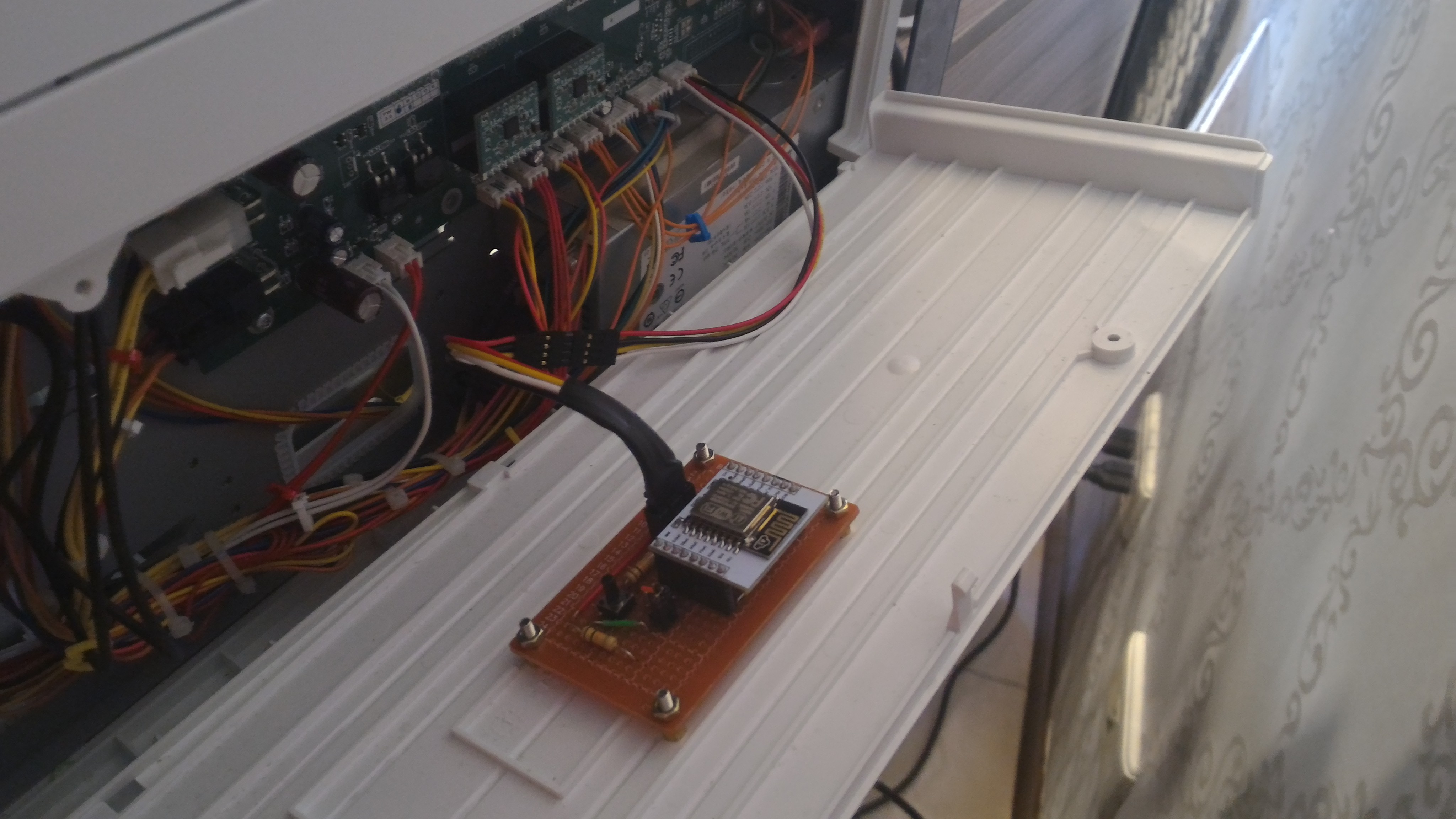
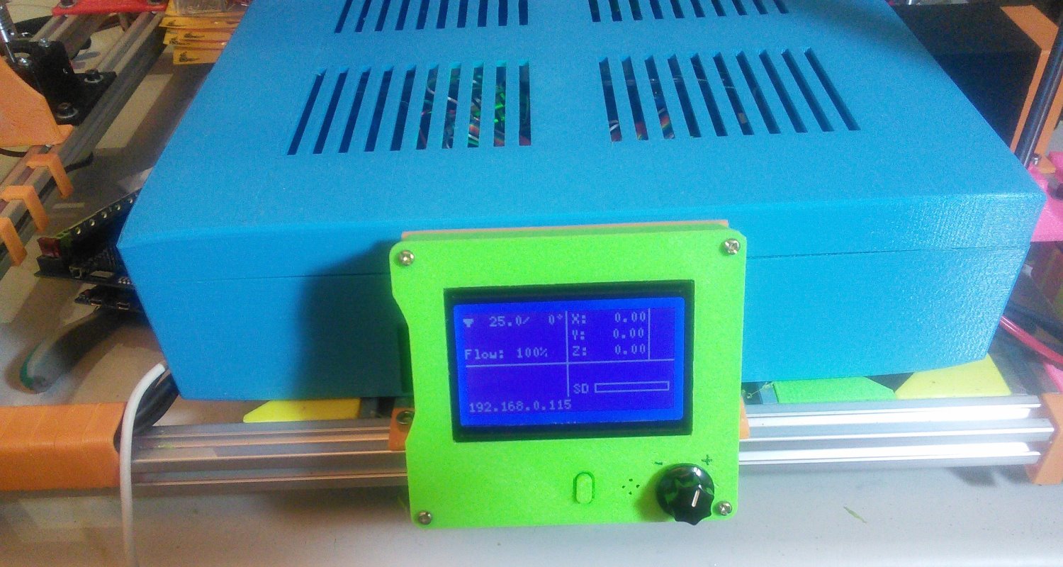
printed cases:
Subsections of Installation
Arduino IDE
Prepare the development environment
-
Please download ide from https://www.arduino.cc/en/software
Warning
Please use the Legacy IDE (1.8.X), the Arduino IDE 2.X was not tested and won’t be supported
-
Install the esp core according your target:
-
ESP8266
Warning
Please use the version 2.5.2 or 2.7.4 only! Do not use any version upper than 2.7.4
-
ESP32
Warning
Please use the version 1.0.4 only! Do not use any version upper than 1.0.4, and only use ESP32 board, other ESP32 flavors(C2, S2, S3, etc) are not supported in this version.
-
Copy the content of the libraries directory to your arduino library directory.
Warning
Do not try any version different than the ones provided, they may not work properly.
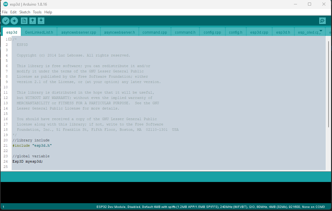
Open esp3d/esp3d.ino file in Arduino IDE
ESP3D configuration
Open esp3d/config.h and set features you want.
//Customize ESP3D ////////////////////////////////////////////////////////////////////////
#define ESP8266_MODEL_NAME "ESP8266"
#define ESP8266_MODEL_URL "http://espressif.com/en/products/esp8266/"
#define ESP32_MODEL_NAME "ESP32"
#define ESP32_MODEL_URL "https://www.espressif.com/en/products/hardware/esp-wroom-32/overview"
#define ESP_MODEL_NUMBER "ESP3D 2.1"
#define ESP_MANUFACTURER_NAME "Espressif Systems"
#define ESP_MANUFACTURER_URL "http://espressif.com"
//default name if no mac address is valid
#define ESP_DEFAULT_NAME "MYESP"
//if commented name will follow mac address 3 last digits
//like ESP_XXXXXX (eg:ESP_028E41) to avoid overlap if several ESP3D
#define ESP_HOST_NAME ESP_DEFAULT_NAME

//To allow webupdate using small updater
//#define USE_AS_UPDATER_ONLY

//FEATURES - comment to disable //////////////////////////////////////////////////////////

//WEB_UPDATE_FEATURE: allow to flash fw using web UI
#define WEB_UPDATE_FEATURE

#ifndef USE_AS_UPDATER_ONLY
//Do we use async webserver or not (currntly deprecated do not enable it yet)
//#define ASYNCWEBSERVER

//SERIAL_COMMAND_FEATURE: allow to send command by serial
#define SERIAL_COMMAND_FEATURE

//TCP_IP_DATA_FEATURE: allow to connect serial from TCP/IP
#define TCP_IP_DATA_FEATURE

//NOTIFICATION_FEATURE : allow to push notifications
#define NOTIFICATION_FEATURE

//MKS TFT WIFI support see Wiki for wiring
//#define MKS_TFT_FEATURE

//MDNS_FEATURE: this feature allow  type the name defined
//in web browser by default: http:\\esp8266.local and connect
#define MDNS_FEATURE

//SSDD_FEATURE: this feature is a discovery protocol, supported on Windows out of the box
#define SSDP_FEATURE

//NETBIOS_FEATURE: this feature is a discovery protocol, supported on Windows out of the box
//#define NETBIOS_FEATURE

//CAPTIVE_PORTAL_FEATURE: In SoftAP redirect all unknow call to main page
#define CAPTIVE_PORTAL_FEATURE

//RECOVERY_FEATURE: allow to use GPIO2 pin as hardware reset for EEPROM, add 8s to boot time to let user to jump GPIO2 to GND
//#define RECOVERY_FEATURE

//DIRECT_PIN_FEATURE: allow to access pin using ESP201 command
#define DIRECT_PIN_FEATURE

//ESP_OLED_FEATURE: allow oled screen output
//#define ESP_OLED_FEATURE

//DHT_FEATURE: send update of temperature / humidity based on DHT 11/22
//#define DHT_FEATURE

//AUTHENTICATION_FEATURE: protect pages by login password
//#define AUTHENTICATION_FEATURE

//WS_DATA_FEATURE: allow to connect serial from Websocket
#define WS_DATA_FEATURE

//TIMESTAMP_FEATURE: Time stamp feature on direct SD  files
//#define TIMESTAMP_FEATURE
#endif //USE_AS_UPDATER_ONLY
//Extra features /////////////////////////////////////////////////////////////////////////

//Workaround for Marlin 2.X coldstart
//#define DISABLE_CONNECTING_MSG

//Serial rx buffer size is 256 but can be extended
#define SERIAL_RX_BUFFER_SIZE 512

//Serial Parameters
#define ESP_SERIAL_PARAM SERIAL_8N1

//which serial ESP use to communicate to printer (ESP32 has 3 serials available, ESP8266 only one)
//Uncomment one only
#define USE_SERIAL_0
//For ESP32 Only
//#define USE_SERIAL_1
//#define USE_SERIAL_2

//Pins Definition ////////////////////////////////////////////////////////////////////////
//-1 means use default pins of your board what ever the serial you choose
#define ESP_RX_PIN -1
#define ESP_TX_PIN -1

#ifdef RECOVERY_FEATURE
//pin used to reset setting
#define RESET_CONFIG_PIN 2
#endif

#ifdef DHT_FEATURE
#define ESP_DHT_PIN 2
#endif

//Pins where the screen is connected
#ifdef ESP_OLED_FEATURE
#define OLED_DISPLAY_SSD1306  // OLED Display Type: SSD1306(OLED_DISPLAY_SSD1306) / SH1106(OLED_DISPLAY_SH1106), comment this line out to disable oled
#define OLED_PIN_SDA  4  //5 //SDA;  // i2c SDA Pin
#define OLED_PIN_SCL  15  //4 //SCL;  // i2c SCL Pin
#define OLED_ADDR   0x3c
#define HELTEC_EMBEDDED_PIN 16 //0 to disable
#define OLED_FLIP_VERTICALY 1 //0 to disable
#endif
For ESP8266 with 4MB of flash
- Board: Generic ESP8266 Module
- Upload Speed: 115200
- CPU frequency: 160 MHz
- Flash Size: 4M (2M SPIFFS)
- Flash Mode: DIO
- Flash Frequency: 40Mhz
- Reset Method: CK
- Debug Port: Disabled
- Debug Level: None
For ESP8266 with 1MB of flash (this one may not support Web Update due to limited flash size)
- Board: Generic ESP8266 Module
- Upload Speed: 115200
- CPU frequency: 160 MHz
- Flash Size: 1M (128K SPIFFS)
- Flash Mode: DIO
- Flash Frequency: 40Mhz
- Reset Method: CK
- Debug Port: Disabled
- Debug Level: None
For ESP32 with 4MB of flash
- Board: ESP32 Dev Module
- Upload Speed: 115200
- CPU frequency: 240 MHz
- Flash Frequency: 80Mhz
- Flash Mode: QIO
- Flash Size: 4MB
- Partition Scheme: Default 4MB with SPIFFS
- Core Debug Level: None
- PSRAM: Disabled
Compile and flash your module
Select the port you device is connected to and select Upload from sketch menu to compile and flash.
Prepare the development environment
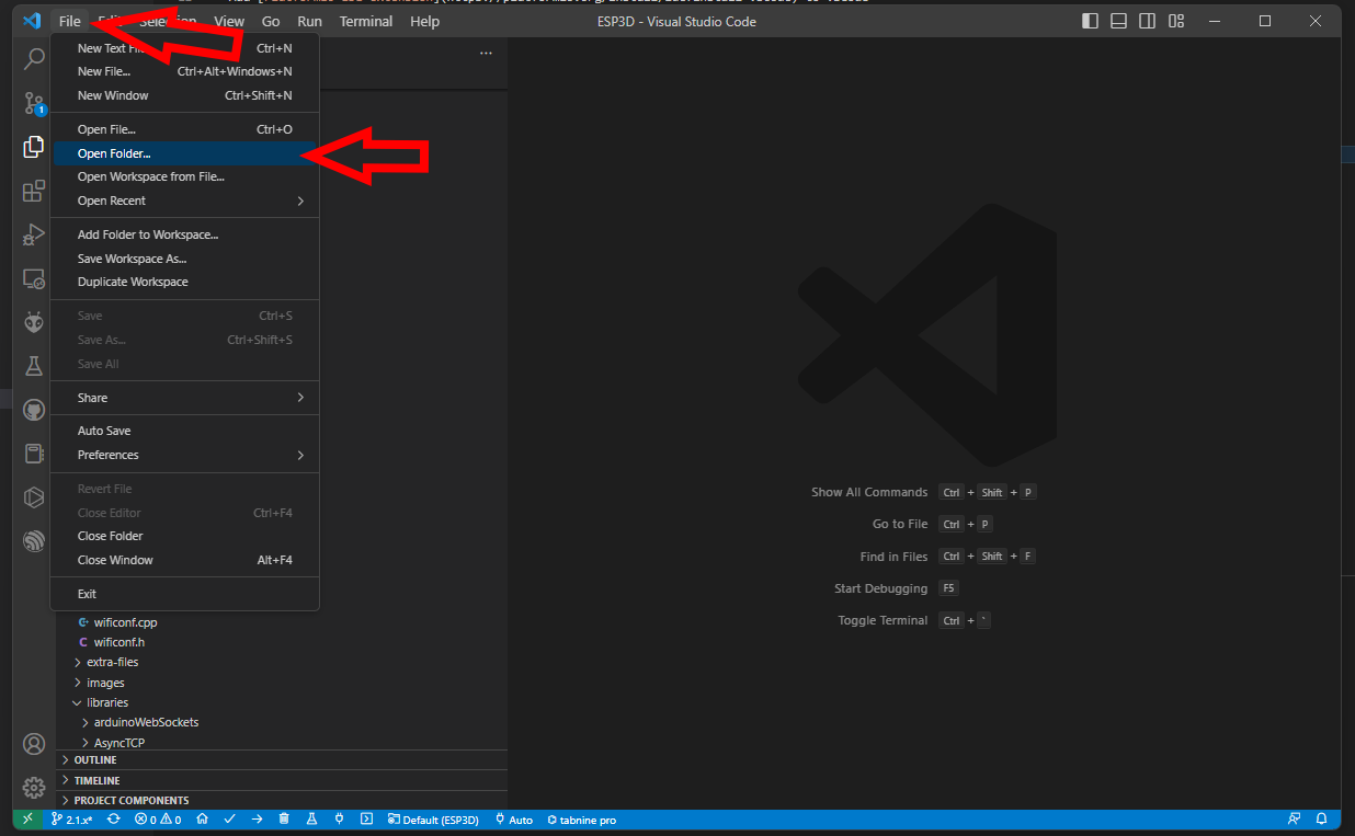
Open the ESP3D directory folder in VSCode
The first time you open the project, vscode need to download all necessary files, so be patient
ESP3D configuration
Open esp3d/config.h and set features you want.
//Customize ESP3D ////////////////////////////////////////////////////////////////////////
#define ESP8266_MODEL_NAME "ESP8266"
#define ESP8266_MODEL_URL "http://espressif.com/en/products/esp8266/"
#define ESP32_MODEL_NAME "ESP32"
#define ESP32_MODEL_URL "https://www.espressif.com/en/products/hardware/esp-wroom-32/overview"
#define ESP_MODEL_NUMBER "ESP3D 2.1"
#define ESP_MANUFACTURER_NAME "Espressif Systems"
#define ESP_MANUFACTURER_URL "http://espressif.com"
//default name if no mac address is valid
#define ESP_DEFAULT_NAME "MYESP"
//if commented name will follow mac address 3 last digits
//like ESP_XXXXXX (eg:ESP_028E41) to avoid overlap if several ESP3D
#define ESP_HOST_NAME ESP_DEFAULT_NAME

//To allow webupdate using small updater
//#define USE_AS_UPDATER_ONLY

//FEATURES - comment to disable //////////////////////////////////////////////////////////

//WEB_UPDATE_FEATURE: allow to flash fw using web UI
#define WEB_UPDATE_FEATURE

#ifndef USE_AS_UPDATER_ONLY
//Do we use async webserver or not (currntly deprecated do not enable it yet)
//#define ASYNCWEBSERVER

//SERIAL_COMMAND_FEATURE: allow to send command by serial
#define SERIAL_COMMAND_FEATURE

//TCP_IP_DATA_FEATURE: allow to connect serial from TCP/IP
#define TCP_IP_DATA_FEATURE

//NOTIFICATION_FEATURE : allow to push notifications
#define NOTIFICATION_FEATURE

//MKS TFT WIFI support see Wiki for wiring
//#define MKS_TFT_FEATURE

//MDNS_FEATURE: this feature allow  type the name defined
//in web browser by default: http:\\esp8266.local and connect
#define MDNS_FEATURE

//SSDD_FEATURE: this feature is a discovery protocol, supported on Windows out of the box
#define SSDP_FEATURE

//NETBIOS_FEATURE: this feature is a discovery protocol, supported on Windows out of the box
//#define NETBIOS_FEATURE

//CAPTIVE_PORTAL_FEATURE: In SoftAP redirect all unknow call to main page
#define CAPTIVE_PORTAL_FEATURE

//RECOVERY_FEATURE: allow to use GPIO2 pin as hardware reset for EEPROM, add 8s to boot time to let user to jump GPIO2 to GND
//#define RECOVERY_FEATURE

//DIRECT_PIN_FEATURE: allow to access pin using ESP201 command
#define DIRECT_PIN_FEATURE

//ESP_OLED_FEATURE: allow oled screen output
//#define ESP_OLED_FEATURE

//DHT_FEATURE: send update of temperature / humidity based on DHT 11/22
//#define DHT_FEATURE

//AUTHENTICATION_FEATURE: protect pages by login password
//#define AUTHENTICATION_FEATURE

//WS_DATA_FEATURE: allow to connect serial from Websocket
#define WS_DATA_FEATURE

//TIMESTAMP_FEATURE: Time stamp feature on direct SD  files
//#define TIMESTAMP_FEATURE
#endif //USE_AS_UPDATER_ONLY
//Extra features /////////////////////////////////////////////////////////////////////////

//Workaround for Marlin 2.X coldstart
//#define DISABLE_CONNECTING_MSG

//Serial rx buffer size is 256 but can be extended
#define SERIAL_RX_BUFFER_SIZE 512

//Serial Parameters
#define ESP_SERIAL_PARAM SERIAL_8N1

//which serial ESP use to communicate to printer (ESP32 has 3 serials available, ESP8266 only one)
//Uncomment one only
#define USE_SERIAL_0
//For ESP32 Only
//#define USE_SERIAL_1
//#define USE_SERIAL_2

//Pins Definition ////////////////////////////////////////////////////////////////////////
//-1 means use default pins of your board what ever the serial you choose
#define ESP_RX_PIN -1
#define ESP_TX_PIN -1

#ifdef RECOVERY_FEATURE
//pin used to reset setting
#define RESET_CONFIG_PIN 2
#endif

#ifdef DHT_FEATURE
#define ESP_DHT_PIN 2
#endif

//Pins where the screen is connected
#ifdef ESP_OLED_FEATURE
#define OLED_DISPLAY_SSD1306  // OLED Display Type: SSD1306(OLED_DISPLAY_SSD1306) / SH1106(OLED_DISPLAY_SH1106), comment this line out to disable oled
#define OLED_PIN_SDA  4  //5 //SDA;  // i2c SDA Pin
#define OLED_PIN_SCL  15  //4 //SCL;  // i2c SCL Pin
#define OLED_ADDR   0x3c
#define HELTEC_EMBEDDED_PIN 16 //0 to disable
#define OLED_FLIP_VERTICALY 1 //0 to disable
#endif
Select the target in VSCode
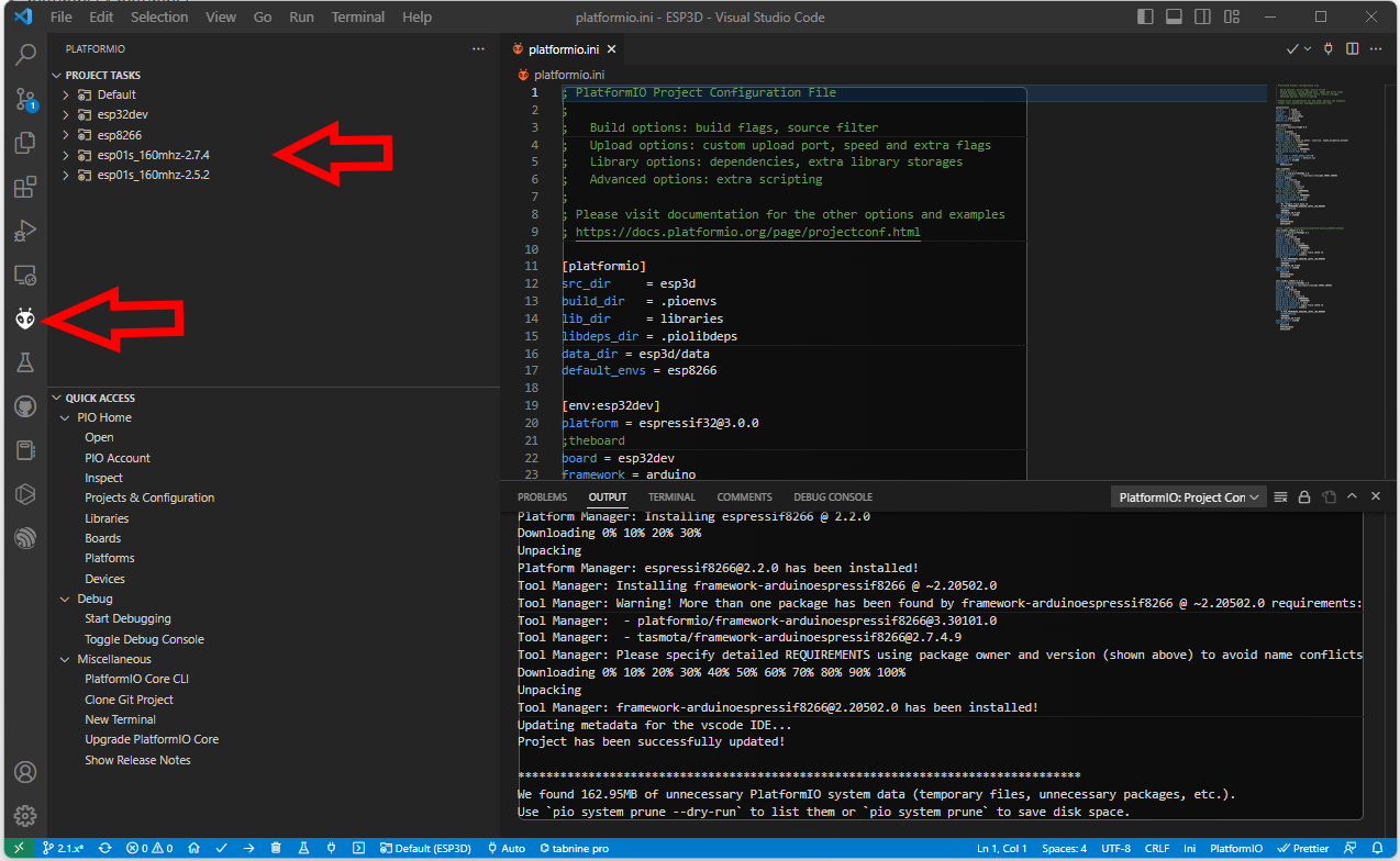
- [env:esp32dev] for ESP32 boards
- [env:esp8266] for ESP8266 boards with 4MB flash
- [env:esp01s_160mhz-2.7.4] for ESP8266 boards with 1MB flash
Compile and flash your module
Use Upload and monitor from the target environment you selected to compile and flash your module.
Hardware connection
Connection between ESP and printer board needs 4 wires:
- ESP Tx needs to connect to Rx on MCU of printer board.
- ESP Rx needs to connect to Tx on MCU of printer board.
- You also need to power supply ESP board with with GND and 3V3 or 5V.
Connecting ESP board to target board
Be aware that ESP MCU is 3.3V on GPIO pin and some target board can be 3.3V and others 5V, so you may not be able to directly connect ESP board to target board.
Disclaimer : this wiki is for reference - you are responsible of your board supporting or not 5V, we are not responsible for any damage of wrong wiring.
ESP32 and ESP8266 MCU are only supporting 3.3V. Power supply them with 5V will likelly fry them immediatelly. As MCU is supplied at 3.3V, Tx and Rx signals will be at 3.3V even when board is supplied with 5V. Wether Rx pin is supporting 5V is controversial so we will keep on the safe side and only take datahseet as reference. It’s not recommended to have any signal (including Rx) be higher than power supply (3.3V here).
There are several points to take care. One should check that
- MCU1 Tx voltage is lower than MCU2 supply voltage
- Voh_min of Tx is higher than Vih_min of Rx (to check both ways)
- Vol_max of Tx is lower than Vil_max of Rx (to check both ways)
1 is mandatory and resistor voltage divider bridge or level shiffter is recommended
2 & 3 are not destructive there is just a slight risk signals are not read correctly. But it will work in most case as the limit values given by datasheets are rarelly met in mild conditions (using near 25°C and low current flowing from Tx to Rx)
For the divider bridge a value of R1=1k and R2=2.2k will be fine.
You could also use 10k and 22k or anything near a factor 2.
Connection diagrams for some printers and ESP boards
Printer motherboards
Anet boards up to v1.5
You will also have to unsolder the resistors R52 and R53 – they are zero ohm resistors, and serve no other purpose than connecting the atmega chip directly to the onboard USB to UART converter (the CH340 chip). Do it VERY careful – you don’t want to damage your board. If you don’t feel confident – don’t do it.
Now prepare the printer’s motherboard. It requires a simple modification, that does not interfere with it’s operation afterwards – just solder 3 pin x 2 row male header on J8, and add 2 jumpers (or jumper wires) as shown on the picture:
Connect the ESP to J3 repsecting pinout
| ESP |
J3 |
| Tx |
Rx |
| Rx |
Tx |
| GND |
GND |
| VCC |
3.3V |
| CH_PD |
3.3V |
For more Info check lokster | space
For connecting version 1.7 Anet boards
Unlike older boards this board does not require you to remove any resistors.
You will have to solder two wires from number 9 and number 10 its recommender to connect these to pin 1 and 2 of J3 connector.
Anycubic i3 mega - Trigorilla 8bit board
To connect the ESP12e to the UART0. (Credits:197-murdock).
(Green = RX, Blue = TX)
5V (buck to 3.3v if directly connect to ESP - most development ESP boards already have this voltage limited built-in - but check!) and GND can be taken from the AUX3 exposed connector.
UART0 is normally used by USB port so don’t use both together - so this hack piggybacks on that same port at UART level.
AZSMZ LCD board
AZSMZ-mini board
If you don’t have the soldering skills to grab the connectors from the unpopulated ethernet connection, you can also get 3.3v and GND from the ISP header (bottom left on the diagram above).
Azteeg X5 mini board
BIQU KFB2.0 board
all in one Ramps1.4/Mega2560 R3 controller based
Creality CR10 Ender 3 board
For the Sanguino based CR-10 and Ender printers you will need to solder to any of the via circled (can also be done in the backside of board), or to the legs of the Arduino or ftdi. Connect TX from the board to RX of Wemos D1 mini and RX from board to TX of Wemos D1 mini. 5v and GND are located in the six pin header next to the LCD connector.
Since soldering might be difficult because the solder points are so close to each other, another option is to scrape off the insulation from the traces on the backside and solder there. Be extra careful not to scrape the surrounding ground plane. You need suitable fine scraping tools for this. The picture below shows an Ender-2 PCB.
Creality Ender 4 board
You will need to solder to small circle, or to the legs of the ATmega2560 (RXD0 pin 2, TXD0 pin 3)
Davinci 1.0/2.0 board
Davinci 1.0A board
Alternate Module placement for increased WiFi range (outside metal chassis, antenna has vertical polarization)
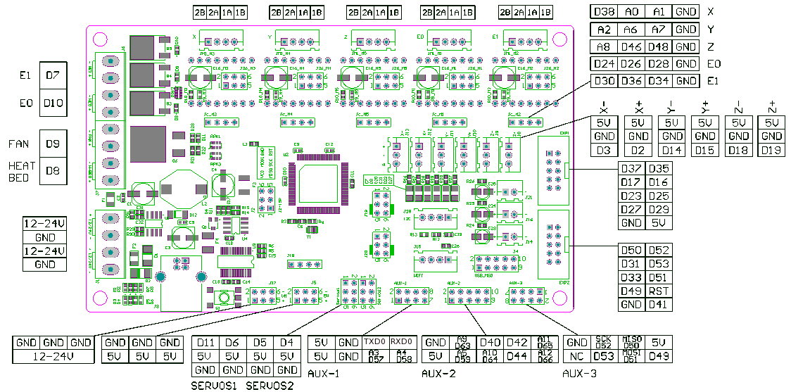
MKS boards
To connect the ESP3D to the MKS GEN v1.2 (but the v1.3 and above 1.4 is the most used today).
An ESP12E with the standard schematics, the two resistor connected to the RX pin are substituted by a 1N4148 diode, like in the Adafruit Huzzah board.
ESP12E is connected to the AUX1
ESP12E RX is connected to the pin NEAR GND of the upper row (Marked TXD on pinout.)
ESP12E TX is connected to the adiacent pin at the end of the upper row (Marked RXD on pinout.)
MKS Smoothieware board
RADDS board
RAMPS 1.4/Re-ARM board
Ramps 1.4 can be used on Arduino Mega (repetier/marlin) and Re-ARM for ramps boards (smoothieware/marlin)
Alternative pins if use Re-ARM (J4/UART port)
Smoothieboard board
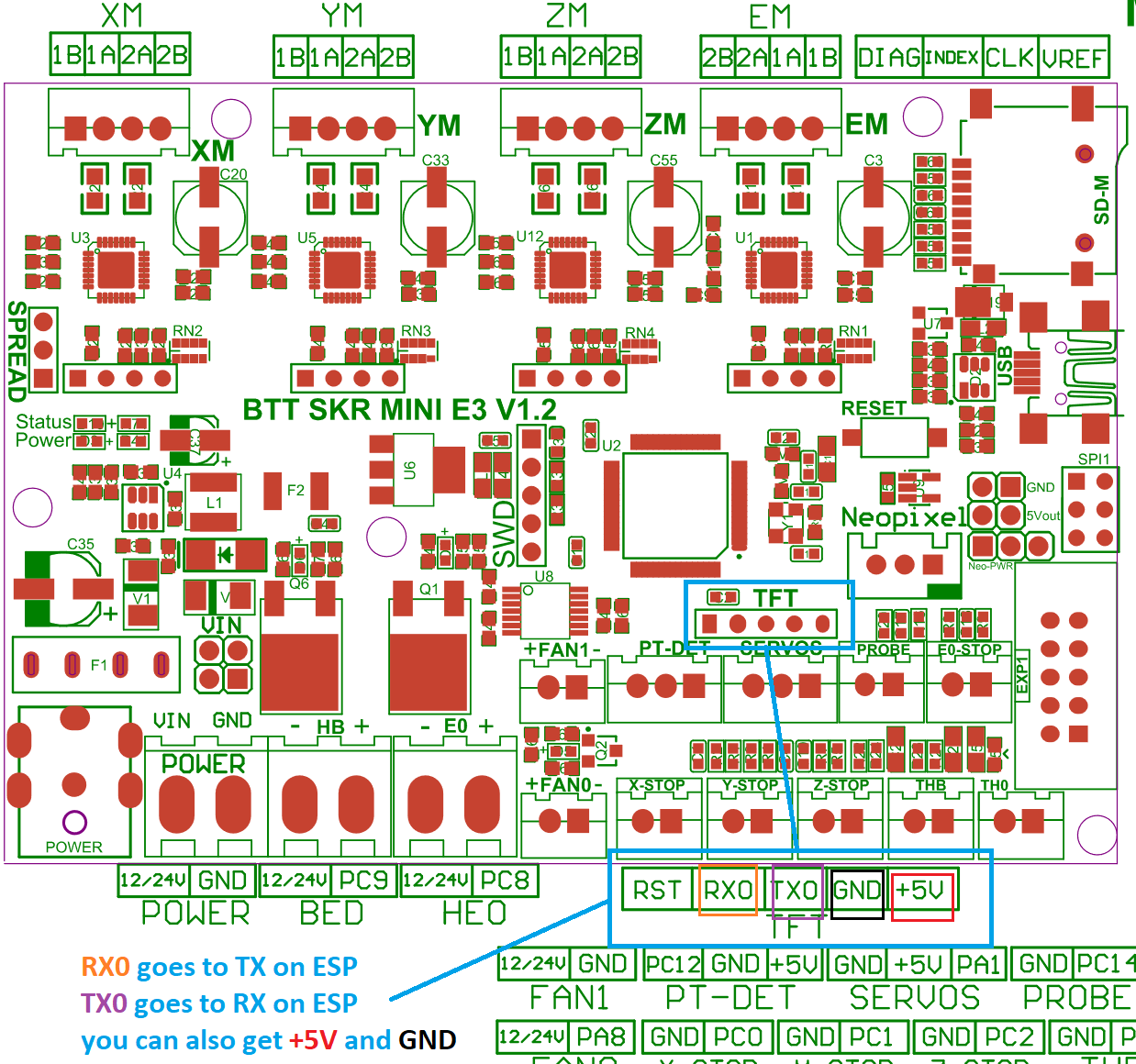
SKR Mini E3 board
This board is from Bigtreetech and went through various hardware revisions; all of them still feature a TFT pin header which is where you can tap the TX and RX needed. The wiring below is made with a 1.2 board, but the same applies for the other revisions as well; if you need the exact schematic for your mainboard version, you can check Bigtreetech’s github repository.
You literally cannot miss it because the TFT connector is labeled on the board; you can use dupont connectors for the wiring job, no soldering skills needed as long as your ESP comes with pre soldered headers.
Just a heads up: the TFT connector provides 5V DC, so be sure to provide them on the correct ESP pin and, most importantly, if your ESP can work with 5 volts as input. You should also pay attention on the board orientation in the schematic, although I oriented it the same way as the actual picture on the left so it’s easier for you.
Weedo Tina2 board
This printer is also brand labelled as Monoprice MP cadet 3D printer
In marlin this connection is serial port 3.
Note the Mega2560 is 5V powered and ESP is 3V3 powered.
For printer boards not listed here
Vast majority of printers have an USB port that is converted to UART before going to MCU. Many printers also have additional (unused) UART port you can use. When possible, always use the additional port for connecting ESP to printer board. When no additional UART port is available you might use the Tx and Rx lines between USB/UART converter and MCU but it’s recommended to cut (in a reversible way) the line to USB/UART converter to avoid conflicts.
If the board is ATmega based the simplest way to find a usable UART port for the ESP is to open ATmega datasheet.
ESP boards
ESP-01
- Use GPIO2 to ground to reset all settings in hard way - 2-6 sec after boot / not before!! Set GPIO2 to ground before boot change boot mode and go to special boot that do not reach FW. Currently boot take 10 sec - giving 8 seconds to connect GPIO2 to GND and do an hard recovery for settings
- Use GPIO0 to ground to be in update mode
ESP-01 serial wifi module
more info about the Breakout PCB: keyestudio
ESP-12E/F
ESP need 3.3v, it is not 5v tolerant, if printer board use more than 3.3V like 5V on ramps.
you can also use Logic LevelConverter Bi-Directional
In order to flash some ESP12E/F boards via their UART interface, the following pins need to be connected:
- VCC to GPIO2
- GND to GPIO0
This has been tested with ESP-12-E boards labeled “ESP8266 For ESP3D FYSETC.COM”
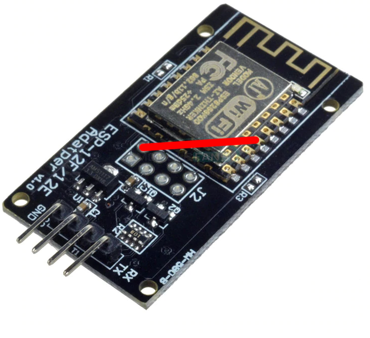
ESP 12F serial wifi module
ESP-12F based serial wifi module (eg from aliexpress ) contains built in 2-way levelshifter/bi-directional logic level converter. So it can be powered via 5V uart from the target’ motherboard.
- We need to manualy ground the
IO0 while powering up to start in flash mode while powering up (there is no switch for that, neither for reset)
- Use FTDI adapter as usb2serial
- Need to see in console/serial monitor boot mode is (1,7).
- baudrate: 74880
rst cause:2, boot mode:(3,7)
- Then flash like other esp based board for esp3d
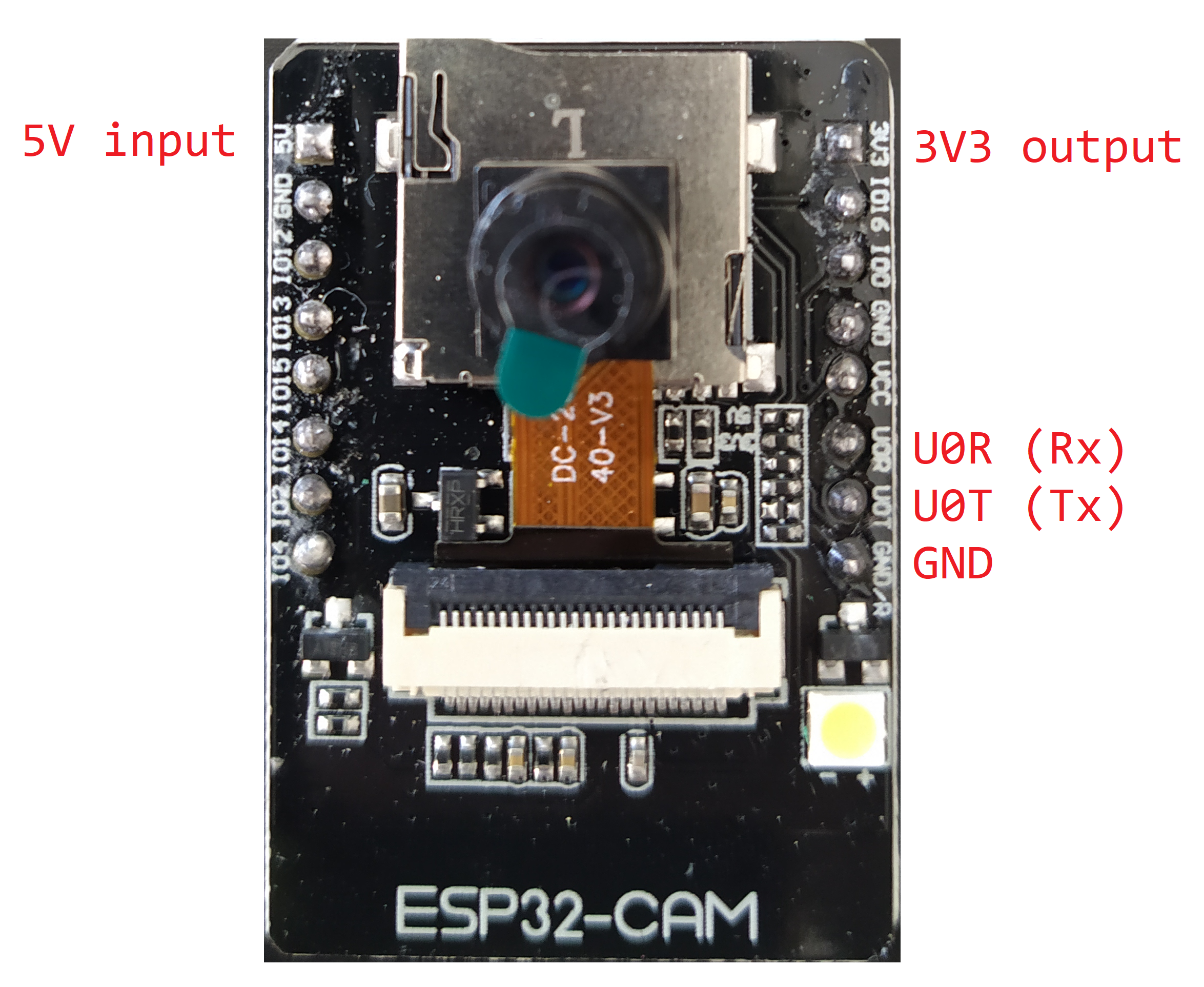
ESP32-Cam
Note: 5V is power supply input and 3V3 is output from regulator. UART Tx and RX signals will be 3.3V
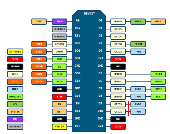
NodeMCU V2/V3
Sonoff
Relay is connected by GPIO12, it can be handled using ESP201 command:
*Get/Set pin value
[ESP201]P<pin> V<value> [PULLUP=YES RAW=YES]
if no V<value> get P<pin> value
if V<value> 0/1 set INPUT_PULLUP value, but for GPIO16 INPUT_PULLDOWN_16
GPIO1 and GPIO3 cannot be used as they are used for serial
if PULLUP=YES set input pull up, if not set input
if RAW=YES do not set pinmode just read value
So [ESP201]P12 V0 should be off and [ESP201]P12 V1 should be on
Wemos D1 mini
Connection with logic level conveter:
example:
printed cases: