ESP32 boards
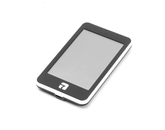
- 3.5' Rotrics
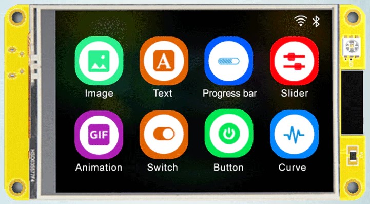
ESP32 3.5' (480x320) TFT
- 3.5' ESP32-3248S035R/C
ESP32 - 3.5' (480x320) TFT
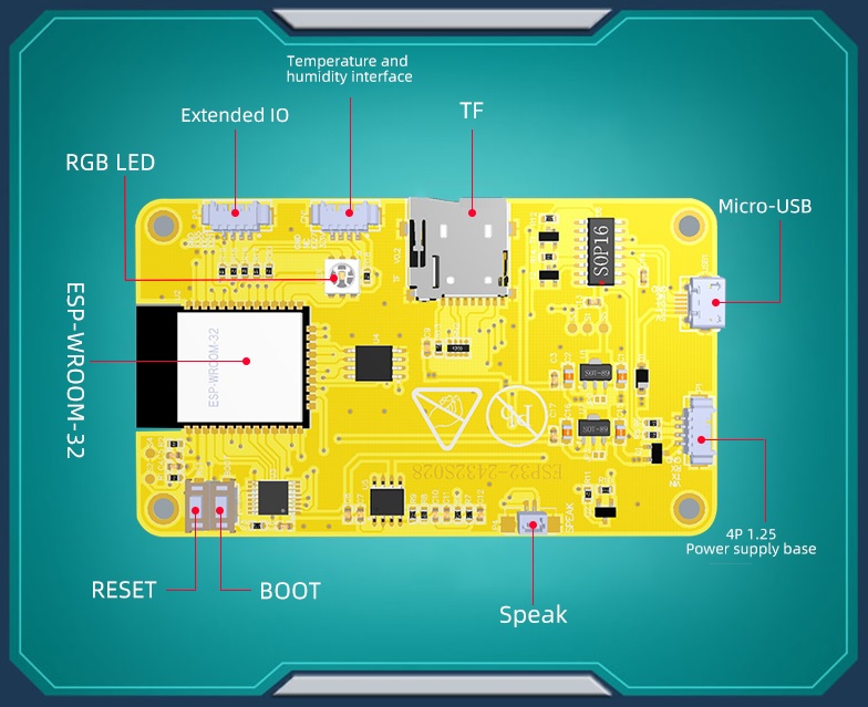
- 2.8' ESP32-2432S028R
ESP32 - 2.8' (320x240) TFT
ESP32 3.5' (480x320) TFT
ESP32 - 3.5' (480x320) TFT
ESP32 - 2.8' (320x240) TFT
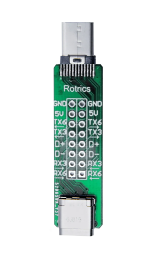
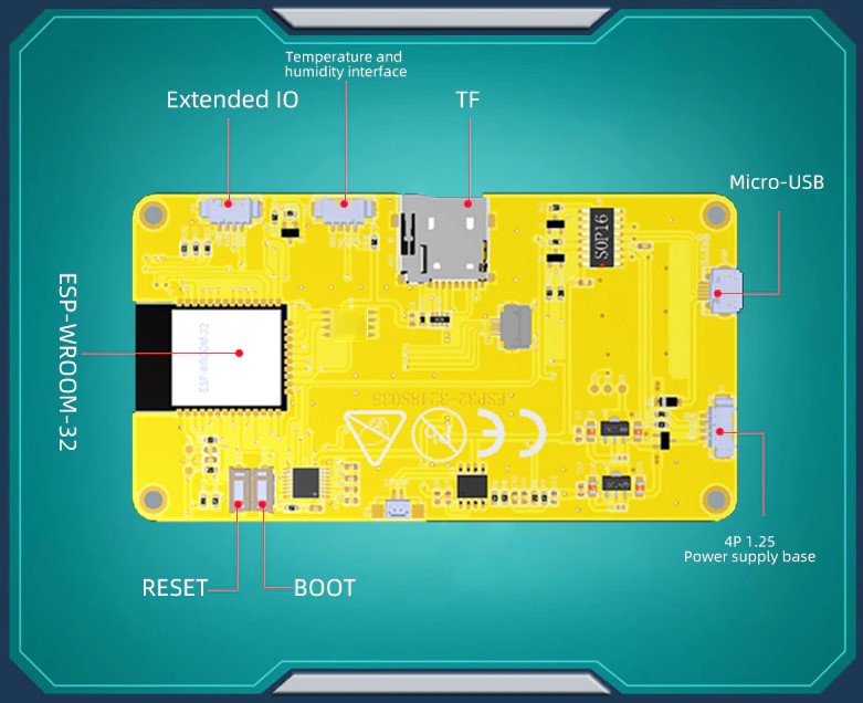
The USB-C connector is actually a raw serial 1 port, not a real USB port.
Serial 1 is the serial port used for communication with other devices.
Serial 0 is the serial port used for programming the ESP32, this port is not easily accessible because connector is not soldered.
So do not try to flash TFT using usb-c connector, it won’t work.
The ESP32 serial 1 TX is on both TX3 of USB connector, and ESP32 serial 1 RX is on both RX3 of USB connector, GND is GND, 5V is 5V, D+, D-, TX6 and RX6 seems not connected.
| Pin | Usage |
|---|---|
| GPIO 0 | GPIO 0 / CODEC_ES8388_I2S_MCLK |
| GPIO 1 | TX 0 |
| GPIO 2 | GPIO 2 / SDIO DAT0 |
| GPIO 3 | RX 0 |
| GPIO 4 | SDIO DAT1 |
| GPIO 5 | CODEC_ES8388_I2S_SCLK |
| GPIO 6 | SPI FLASH |
| GPIO 7 | SPI FLASH |
| GPIO 8 | SPI FLASH |
| GPIO 9 | SPI FLASH |
| GPIO 10 | SPI FLASH |
| GPIO 11 | SPI FLASH |
| GPIO 12 | TFT_BL |
| GPIO 13 | TFT_TOUCH_CS |
| GPIO 14 | SDIO CLK |
| GPIO 15 | SDIO CMD |
| GPIO 16 | |
| GPIO 17 | |
| GPIO 18 | CODEC_ES8388_I2C_SDA - CE(low) wired to GND |
| GPIO 19 | TFT_CS |
| GPIO 21 | TX 1 |
| GPIO 22 | TFT_TOUCH_IRQ |
| GPIO 23 | CODEC_ES8388_I2C_SCL |
| GPIO 25 | CODEC_ES8388_I2S_LRCK |
| GPIO 26 | CODEC_ES8388_I2S_DSDIN |
| GPIO 27 | TFT_DC |
| GPIO 32 | TFT_MOSI |
| GPIO 33 | TFT_SCLK |
| GPIO 34 | TFT_MISO |
| GPIO 35 | CODEC_ES8388_I2S_ASDOUT |
| GPIO 36 | RX 1 |
| GPIO 37 | SD_DETECT (Low) |
| GPIO 38 | |
| GPIO 39 |
| Pin | Usage |
|---|---|
| ROUT1 | |
| LOUT1 | |
| ROUT2 | speaker |
| LOUT2 | |
| RIN2 | |
| LIN2 | |
| RIN1 | |
| LIN1 | microphone |
| ESP Pin | GPIO | Description |
|---|---|---|
| 1 | GND | Ground |
| 2 | VCC | +3V3 |
| 3 | EN | RST / TFT_RST (Reset / LCD) |
| 4 | GPIO36 | SENSOR_VP / RTP_IRQ (Res. Touchscreen) |
| 5 | GPIO39 | SENSOR_VN |
| 6 | GPIO34 | ADC |
| 7 | GPIO35 | Header P3 Pin 3 |
| 8 | GPIO32 | CTP_SCL (Cap. Touchscreen) |
| 9 | GPIO33 | CTP_SDA (Cap. Touchscreen) / RTP_CS (Res. Touchscreen) |
| 10 | GPIO25 | CTP_RST (Cap. Touchscreen) |
| 11 | GPIO26 | AUDIO IN- |
| 12 | GPIO27 | TFT_BL (TFT) |
| 13 | GPIO14 | TFT_SCK (TFT) / RTP_CLK (Res. Touchscreen) |
| 14 | GPIO12 | TFT_SDO (TFT) / RTP_OUT (Res. Touchscreen) |
| 15 | GND | Ground |
| 16 | GPIO13 | TFT_SDI (TFT) / RTP_DIN (Res. Touchscreen) |
| 17 | SHD/SD2 | HOLD (SPI Flash / PSRAM*) |
| 18 | SWP/SD3 | WP (SPI Flash / PSRAM*) |
| 19 | SCS/CMD | CS (SPI Flash) |
| 20 | SCK/CLK | SCK (SPI Flash) |
| 21 | SDO/SD0 | SO (SPI Flash / PSRAM*) |
| 22 | SDI/SD1 | SI (SPI Flash / PSRAM*) |
| 23 | GPIO15 | TFT_CS (TFT) |
| 24 | GPIO02 | TFT_RS (TFT) |
| 25 | GPIO0 | BOOT_SW |
| 26 | GPIO04 | LED_RGB |
| 27 | GPIO16 | LED_RGB (PSRAM_CS*) |
| 28 | GPIO17 | LED_RGB (PSRAM_SCK*) |
| 29 | GPIO05 | TF_CS (SD Card) |
| 30 | GPIO18 | TF_CLK (SD Card) |
| 31 | GPIO19 | MCU_MISO (SD Card) |
| 32 | NC | NA |
| 33 | GPIO21 | CTP_INT* (Cap. Touchscreen) / Headers: P3 Pin 1, CN1 Pin 2 |
| 34 | RXD0 | RXD2 Header P1 Pin 3 |
| 35 | TXD0 | TXD2 Header P1 Pin 2 |
| 36 | GPIO22 | Header P3 Pin 2 (also Header CN1 Pin 3 on some boards) |
| 37 | GPIO23 | MCU_MOSI (SD Card) |
| 38 | GND | Ground |
| 39 | GND | Ground |
* Requires Hardware Mod
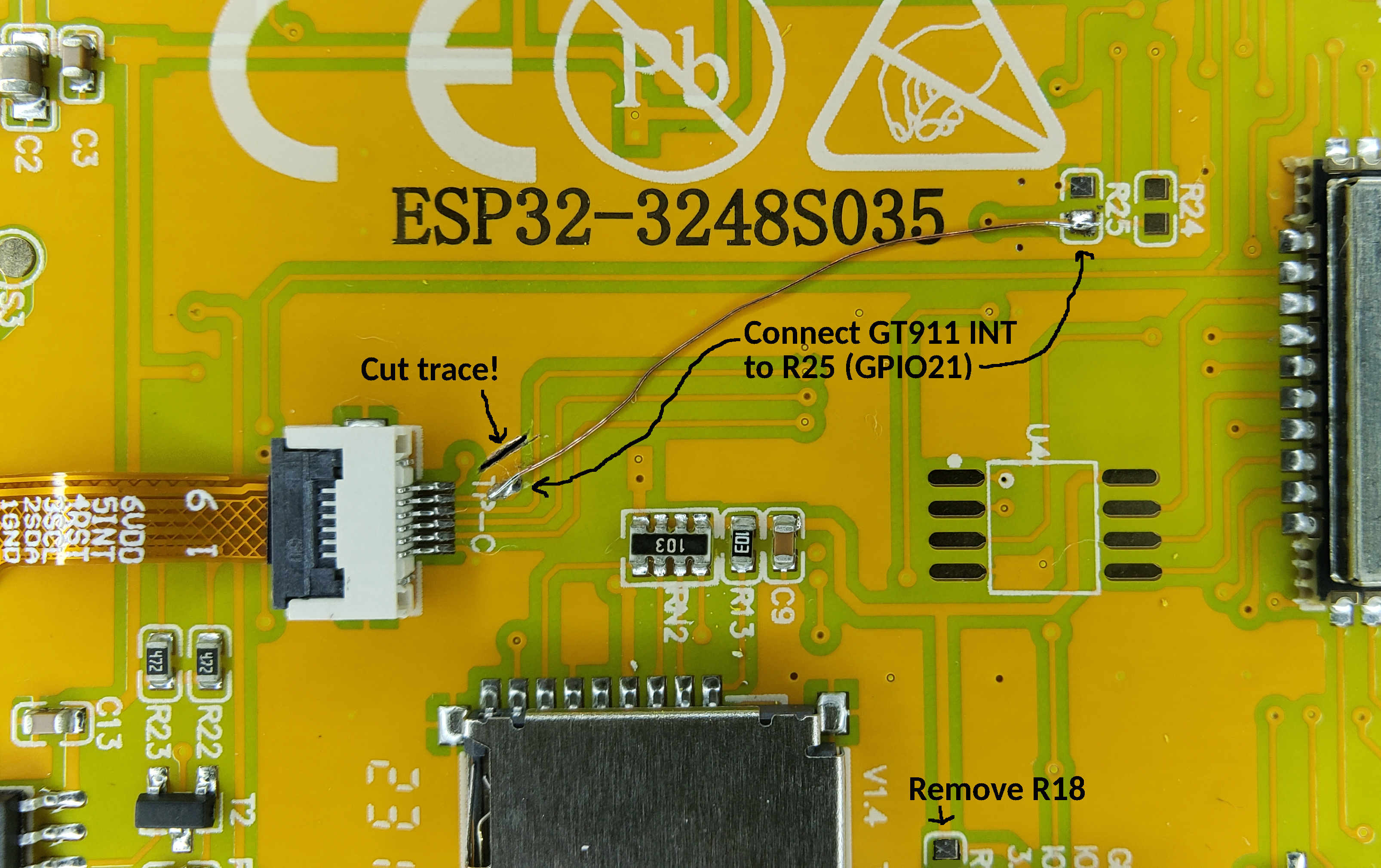
NOTE: This only applies to the screen with the Capacitive touch panel (ESP32_3248S035C)
There is a routing mistake on the ESP32_3248S035C board that accidentally connects the Capacitive Touch Screen’s GT911 Interrupt pin to GND instead of through the R25 jumper to GPIO21. This means that the code has to use polling (by default) instead of hardware interrupts to determine when the screen is being touched. This results in excessive CPU utilization of greater than 80%. Making the below modifications results in a significantly reduced CPU utilization of under 10% on avg (on static screens).
NOTE: Remember to enable the HARDWARE_MOD_GT911_INT option in CMakeLists.txt
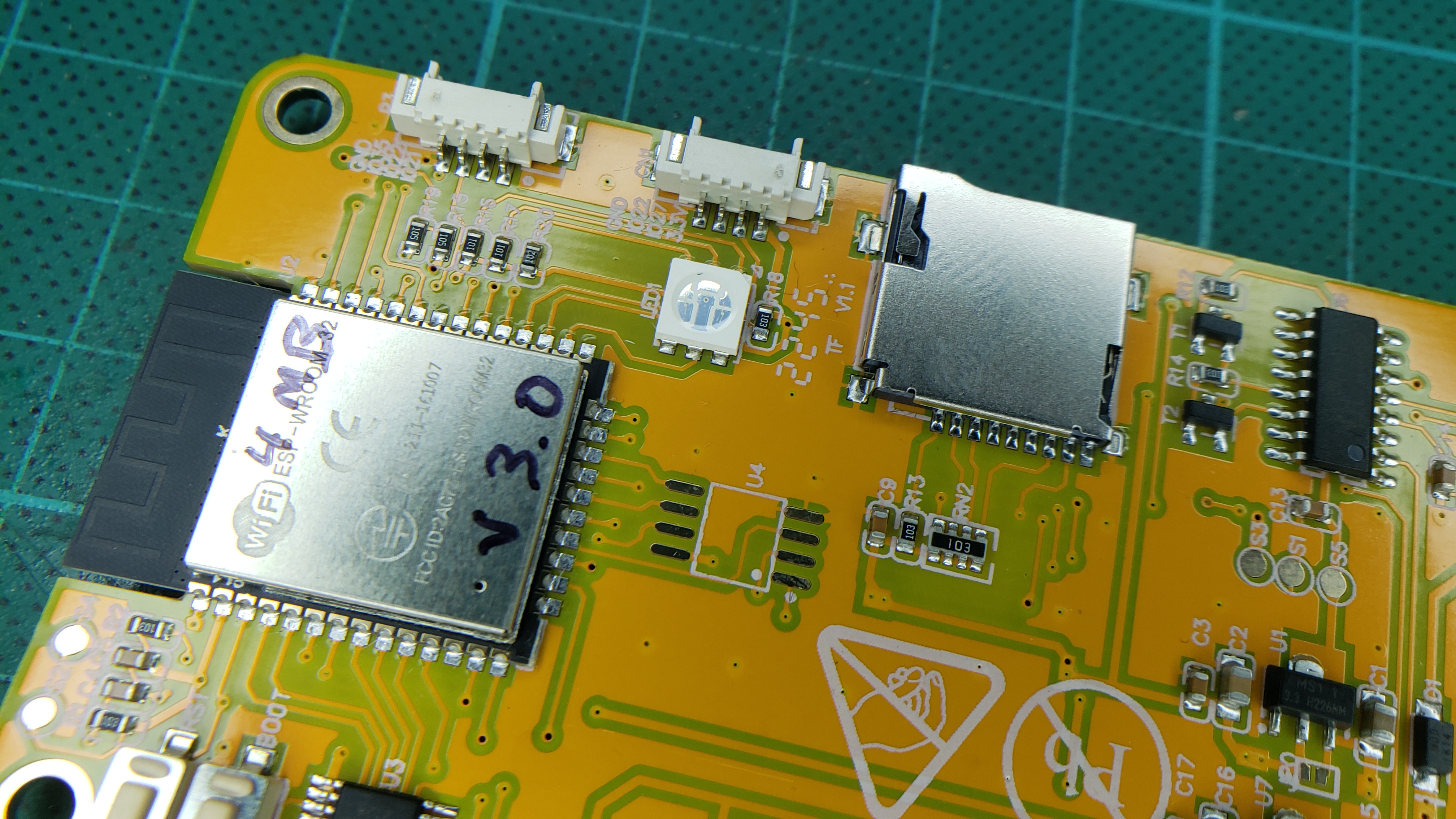
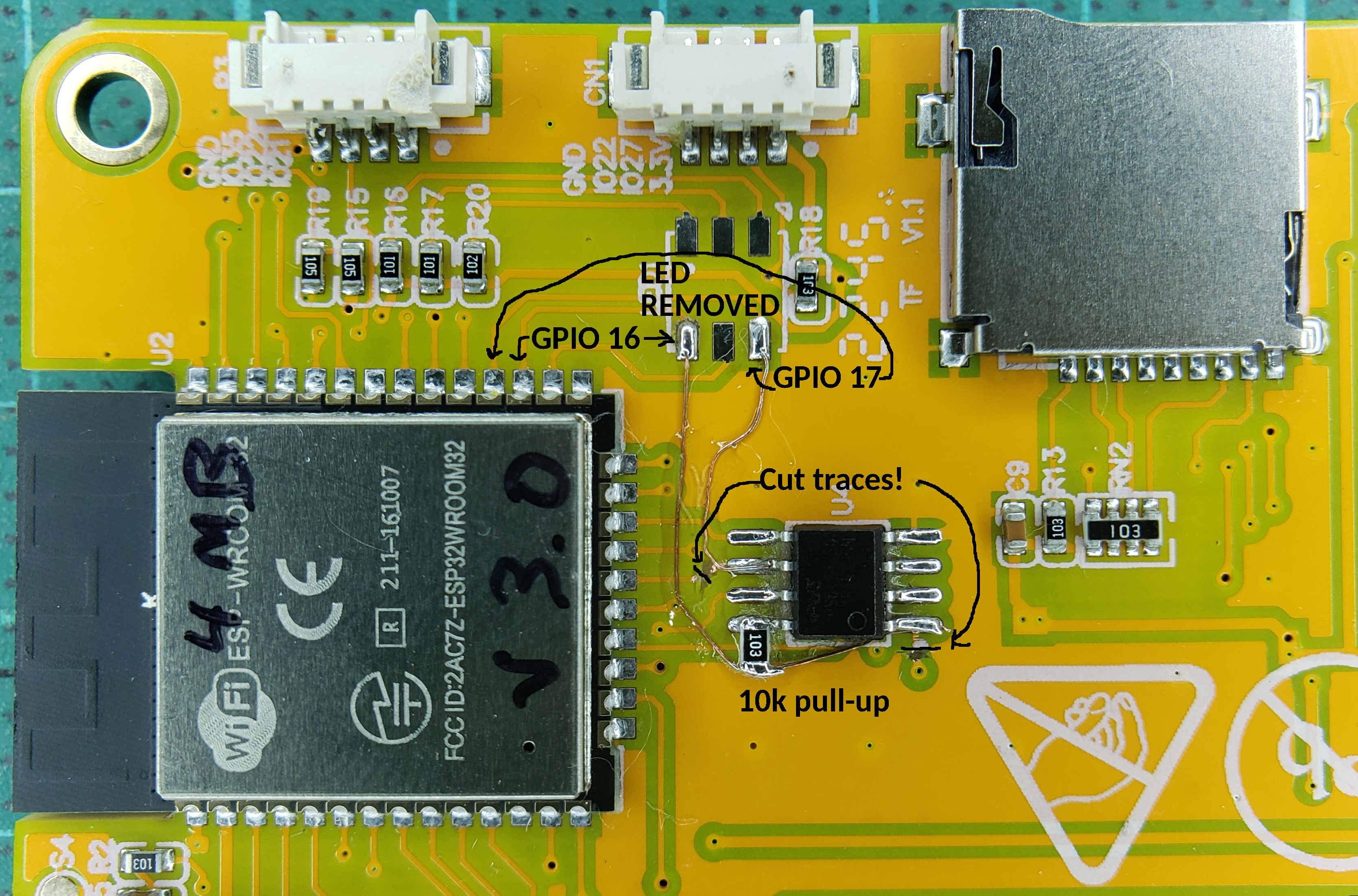
This board has an external SOIC-8 footprint near the ESP32 module that is wired in parallel to the built-in SPI Flash. This can be used (with some modifications) to add an external SPI PSRAM in order to achieve more available memory.
NOTE: There are (at least) two revisions of this board.
In either case, one will first need to acquire a compatible PSRAM IC. This can be desoldered from an existing board (i.e. ESP32-CAM board), or purchased separately. Make sure whatever IC you choose supports 3.3v and at least 80 MHz. Ideally it should support Quad SPI (QIO) as well.
Some compatible 8MB PSRAM ICs are:
NOTE: Remember to choose the correct variant in CMakeLists.txt to enable PSRAM support.
On this revision, the PSRAM must be piggy-backed on top of the external Flash IC.
On this revision, the PSRAM can be soldered to the un-populated SOIC-8 footprint.
| ESP Pin | GPIO | Description |
|---|---|---|
| 1 | GND | Ground |
| 2 | VCC | +3V3 |
| 3 | EN | RST / TFT_RST (Reset / LCD) |
| 4 | GPIO36 | SENSOR_VP / TP_IRQ (Touchscreen) |
| 5 | GPIO39 | SENSOR_VN / TP_OUT (Touchscreen) |
| 6 | GPIO34 | ADC |
| 7 | GPIO35 | Header P3 Pin 3 |
| 8 | GPIO32 | TP_DIN (Touchscreen) |
| 9 | GPIO33 | TP_CS (Touchscreen) |
| 10 | GPIO25 | TP_CLK (Touchscreen) |
| 11 | GPIO26 | AUDIO IN- |
| 12 | GPIO27 | Header CN1 Pin 2 |
| 13 | GPIO14 | TFT_SCK (TFT) |
| 14 | GPIO12 | TFT_SDO (TFT) |
| 15 | GND | Ground |
| 16 | GPIO13 | TFT_SDI (TFT) |
| 17 | SHD/SD2 | HOLD (SPI Flash / PSRAM*) |
| 18 | SWP/SD3 | WP (SPI Flash / PSRAM*) |
| 19 | SCS/CMD | CS (SPI Flash) |
| 20 | SCK/CLK | SCK (SPI Flash) |
| 21 | SDO/SD0 | SO (SPI Flash / PSRAM*) |
| 22 | SDI/SD1 | SI (SPI Flash / PSRAM*) |
| 23 | GPIO15 | TFT_CS (TFT) |
| 24 | GPIO02 | TFT_RS (TFT) |
| 25 | GPIO0 | BOOT_SW |
| 26 | GPIO04 | LED_RGB |
| 27 | GPIO16 | LED_RGB (PSRAM_CS*) |
| 28 | GPIO17 | LED_RGB (PSRAM_SCK*) |
| 29 | GPIO05 | TF_CS (SD Card) |
| 30 | GPIO18 | TF_CLK (SD Card) |
| 31 | GPIO19 | MCU_MISO (SD Card) |
| 32 | NC | NA |
| 33 | GPIO21 | TFT_BL (TFT) / Header P3 Pin 1 |
| 34 | RXD0 | RXD2 Header P1 Pin 3 |
| 35 | TXD0 | TXD2 Header P1 Pin 2 |
| 36 | GPIO22 | Header P3 Pin 2 (also Header CN1 Pin 3 on some boards) |
| 37 | GPIO23 | MCU_MOSI (SD Card) |
| 38 | GND | Ground |
| 39 | GND | Ground |
* Requires Hardware Mod
This board has an external SOIC-8 footprint near the ESP32 module that is wired in parallel to the built-in SPI Flash. This can be used (with some modifications) to add an external SPI PSRAM in order to achieve more available memory.
NOTE: There are (at least) two revisions of this board.
In either case, one will first need to acquire a compatible PSRAM IC. This can be desoldered from an existing board (i.e. ESP32-CAM board), or purchased separately. Make sure whatever IC you choose supports 3.3v and at least 80 MHz. Ideally it should support Quad SPI (QIO) as well.
Some compatible 8MB PSRAM ICs are:
NOTE: Remember to choose the correct variant in CMakeLists.txt to enable PSRAM support.
On this revision, the PSRAM must be piggy-backed on top of the external Flash IC.
On this revision, the PSRAM can be soldered to the un-populated SOIC-8 footprint.