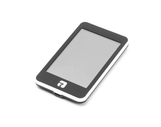
3.5' Rotrics
- ESP32 + SDReader + PSRAM + 3.5’ TFT (480x320) with Resistive touch screen
Specs
- ESP32
- PSRAM: 8MB
- FLASH: 8MB
- Micro-SD card slot (SDIO 1 bit)
- 3.5-inch 480x320 TFT display - ILI9488 (SPI)
- Capacitive touch panel - XPT2046 (SPI)
- Built-in microphone
- Speaker
- 1 USB-C (Serial 1)
- 1 debug port: GND, 5V, EN, GPIO 0, GPIO 2, GPIO 1 (TX), GPIO 3 (RX)
- Power Supply: 5V / 1A
Important
The USB-C connector is actually a raw serial 1 port, not a real USB port.
Serial 1 is the serial port used for communication with other devices.
Serial 0 is the serial port used for programming the ESP32, this port is not easily accessible because connector is not soldered.
So do not try to flash TFT using usb-c connector, it won’t work.
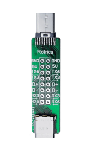
Note about USB-C connector
The ESP32 serial 1 TX is on both TX3 of USB connector, and ESP32 serial 1 RX is on both RX3 of USB connector, GND is GND, 5V is 5V, D+, D-, TX6 and RX6 seems not connected.
Pins
| Pin | Usage |
|---|---|
| GPIO 0 | GPIO 0 / CODEC_ES8388_I2S_MCLK |
| GPIO 1 | TX 0 |
| GPIO 2 | GPIO 2 / SDIO DAT0 |
| GPIO 3 | RX 0 |
| GPIO 4 | SDIO DAT1 |
| GPIO 5 | CODEC_ES8388_I2S_SCLK |
| GPIO 6 | SPI FLASH |
| GPIO 7 | SPI FLASH |
| GPIO 8 | SPI FLASH |
| GPIO 9 | SPI FLASH |
| GPIO 10 | SPI FLASH |
| GPIO 11 | SPI FLASH |
| GPIO 12 | TFT_BL |
| GPIO 13 | TFT_TOUCH_CS |
| GPIO 14 | SDIO CLK |
| GPIO 15 | SDIO CMD |
| GPIO 16 | |
| GPIO 17 | |
| GPIO 18 | CODEC_ES8388_I2C_SDA - CE(low) wired to GND |
| GPIO 19 | TFT_CS |
| GPIO 21 | TX 1 |
| GPIO 22 | TFT_TOUCH_IRQ |
| GPIO 23 | CODEC_ES8388_I2C_SCL |
| GPIO 25 | CODEC_ES8388_I2S_LRCK |
| GPIO 26 | CODEC_ES8388_I2S_DSDIN |
| GPIO 27 | TFT_DC |
| GPIO 32 | TFT_MOSI |
| GPIO 33 | TFT_SCLK |
| GPIO 34 | TFT_MISO |
| GPIO 35 | CODEC_ES8388_I2S_ASDOUT |
| GPIO 36 | RX 1 |
| GPIO 37 | SD_DETECT (Low) |
| GPIO 38 | |
| GPIO 39 |
CODEC_ES8388
| Pin | Usage |
|---|---|
| ROUT1 | |
| LOUT1 | |
| ROUT2 | speaker |
| LOUT2 | |
| RIN2 | |
| LIN2 | |
| RIN1 | |
| LIN1 | microphone |