Subsections of Main boards
Anet boards up to v1.5 and 1.7
Anet boards up to v1.5
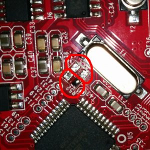
You will have to unsolder the resistors R52 and R53 – they are zero ohm resistors, and serve no other purpose than connecting the atmega chip directly to the onboard USB to UART converter (the CH340 chip). Do it VERY careful – you don’t want to damage your board. If you don’t feel confident – don’t do it.
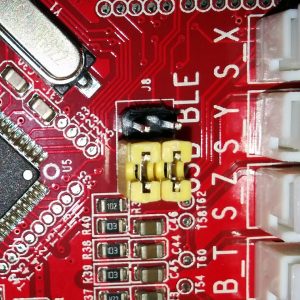
Prepare the printer’s motherboard. It requires a simple modification, that does not interfere with it’s operation afterwards – just solder 3 pin x 2 row male header on J8, and add 2 jumpers (or jumper wires) as shown on the picture:
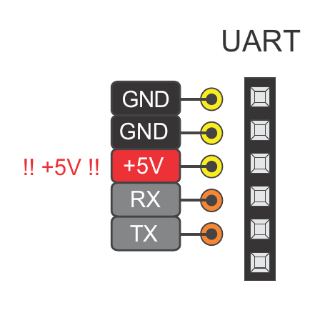
Connect the ESP to J3 repsecting pinout
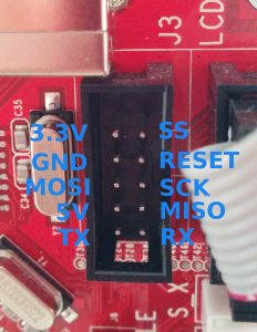
Pinout
| ESP |
J3 |
| Tx |
Rx |
| Rx |
Tx |
| GND |
GND |
| VCC |
3.3V |
| CH_PD |
3.3V |
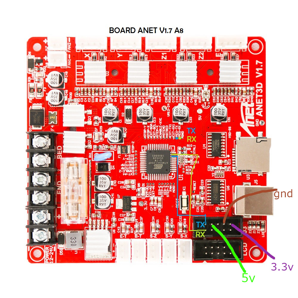
Anet boards v1.7
Unlike older boards this board does not require you to remove any resistors.
You will have to solder two wires from number 9 and number 10 its recommender to connect these to pin 1 and 2 of J3 connector.
|
|
| Board pins voltage |
5V |
| Board firmware |
Marlin |
| Board configuration note |
None, it use same serial as USB port so don’t use both together |
| ESP3D configuration note |
Raw serial, no SD |
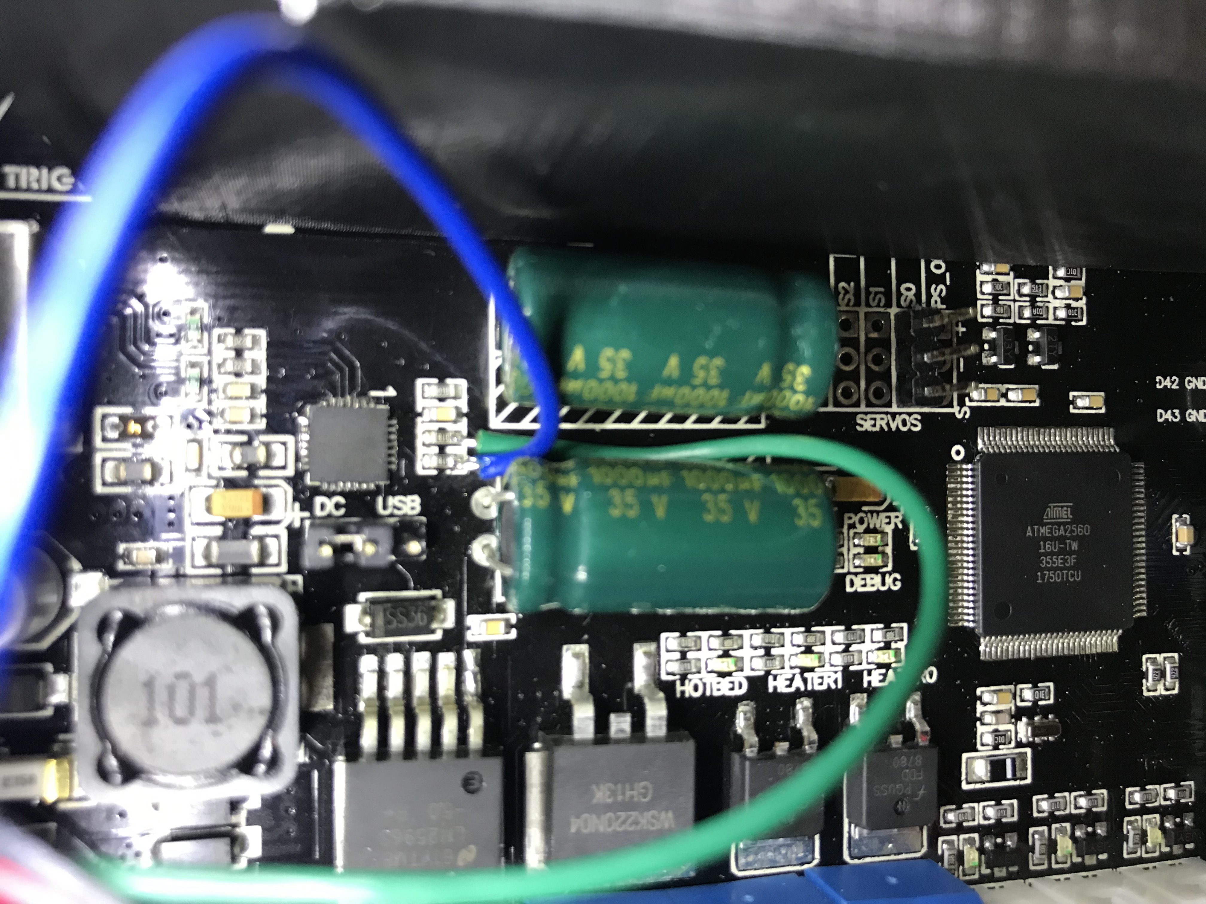
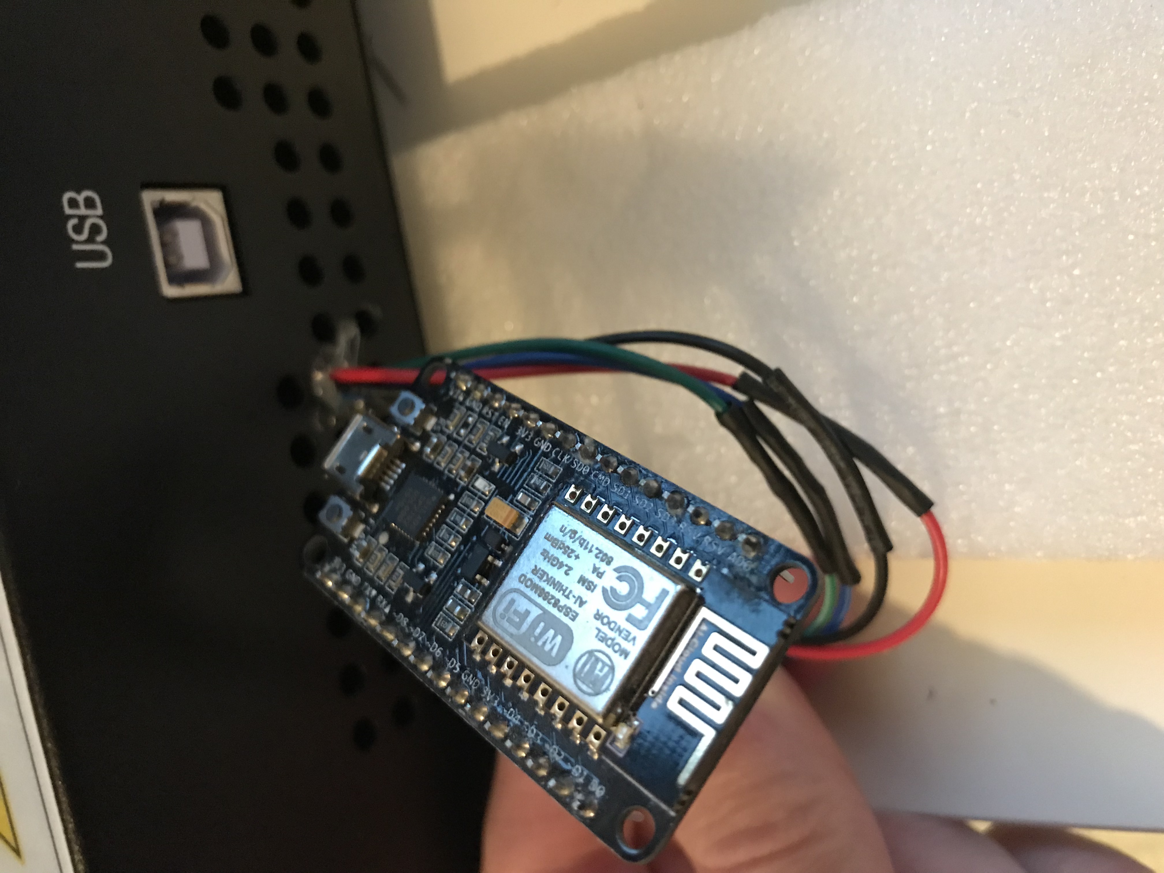
Anycubic i3 mega - Trigorilla 8bit board
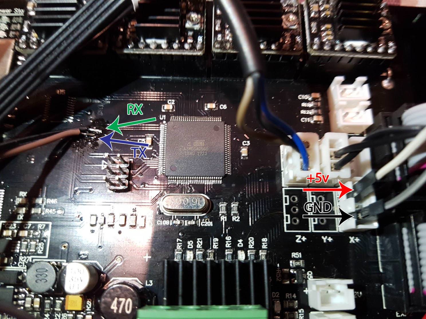
To connect the ESP12e to the UART0. (Credits:197-murdock).
(Green = RX, Blue = TX)
GND can be taken from the AUX3 exposed connector.
|
|
| Board pins voltage |
5V |
| Board firmware |
Marlin |
| Board configuration note |
None, it use same serial as USB port so don’t use both together |
| ESP3D configuration note |
Raw serial, no SD |
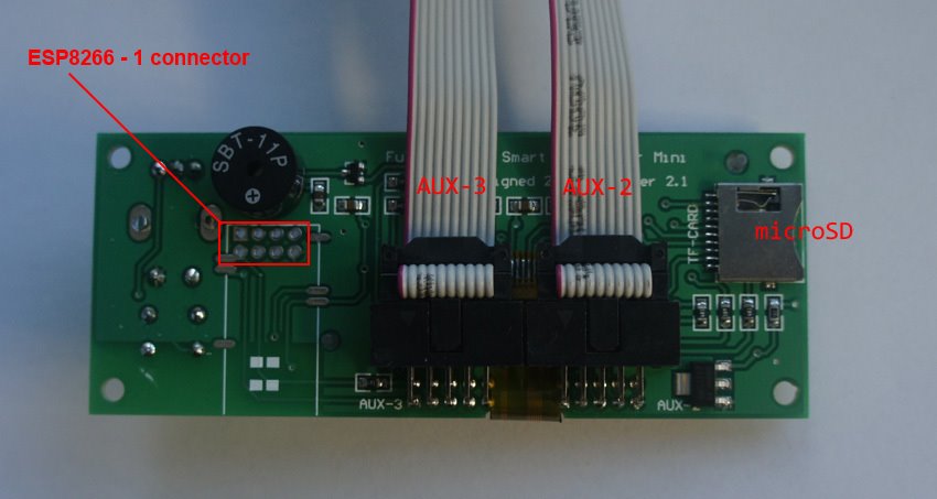
AZSMZ LCD board
The board has footprint for an ESP01 connector
|
|
| Board pins voltage |
3.3v |
| Board firmware |
Smoothieware |
| Board configuration note |
Enable second serial port in the config.txt |
| ESP3D configuration note |
Raw serial, no SD |
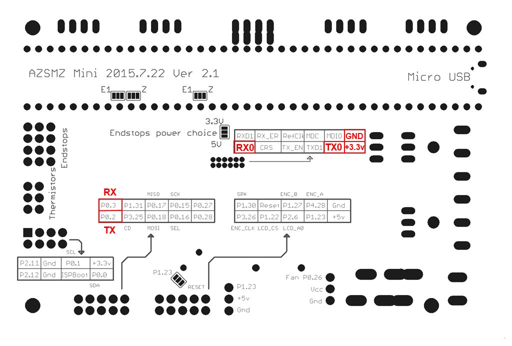
AZSMZ mini board
If you don’t have the soldering skills to grab the connectors from the unpopulated ethernet connection, you can also get 3.3v and GND from the ISP header (bottom left on the diagram above).
|
|
| Board pins voltage |
3.3v |
| Board firmware |
Smoothieware |
| Board configuration note |
Enable second serial port in the config.txt |
| ESP3D configuration note |
Raw serial, no SD |
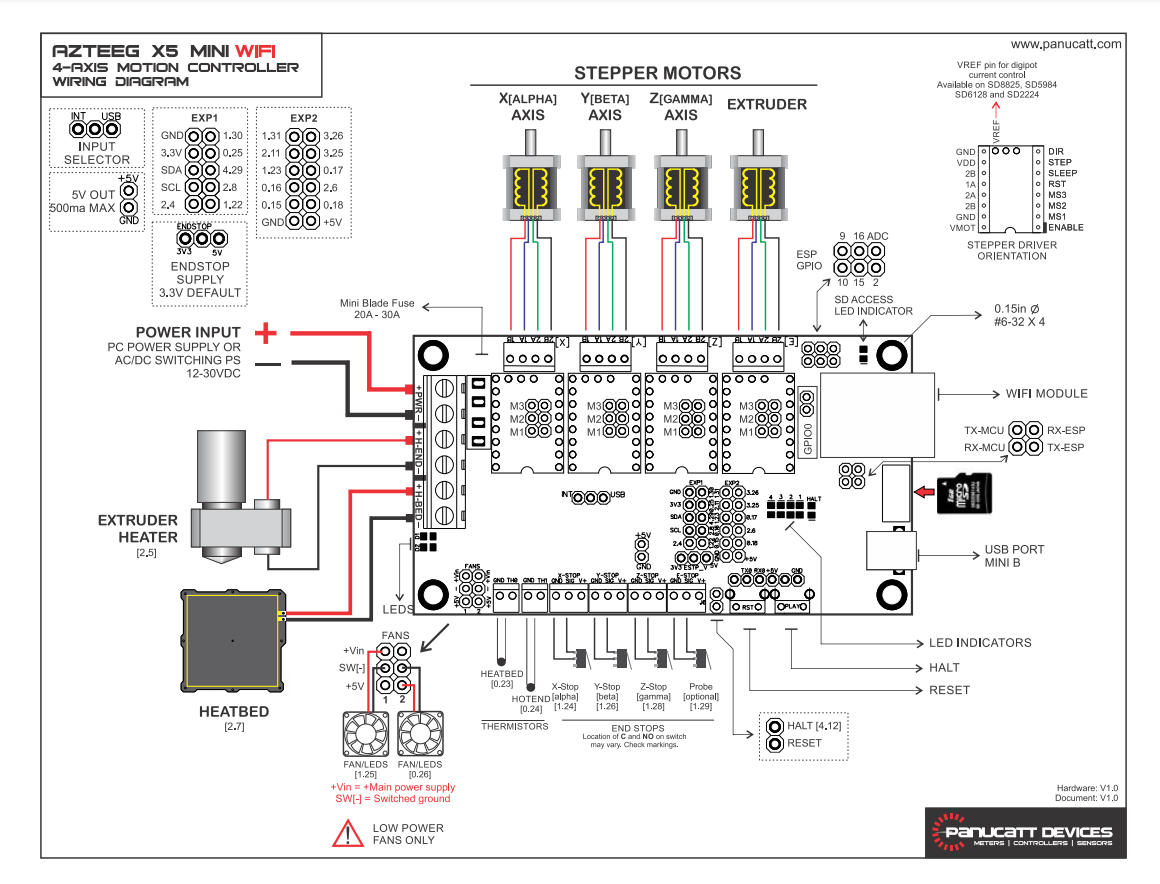
Azteeg X5 mini board
The board has an ESP-12E module on board
|
|
| Board pins voltage |
3.3v |
| Board firmware |
Smoothieware |
| Board configuration note |
Enable second serial port in the config.txt |
| ESP3D configuration note |
Raw serial, no SD |
BIQU KFB2.0 board
The board is an all in one Ramps1.4/Mega2560 R3 controller based
|
|
| Board pins voltage |
5v |
| Board firmware |
Marlin |
| Board configuration note |
Enable second serial port in the marlin configuration file |
| ESP3D configuration note |
Raw serial, no SD |
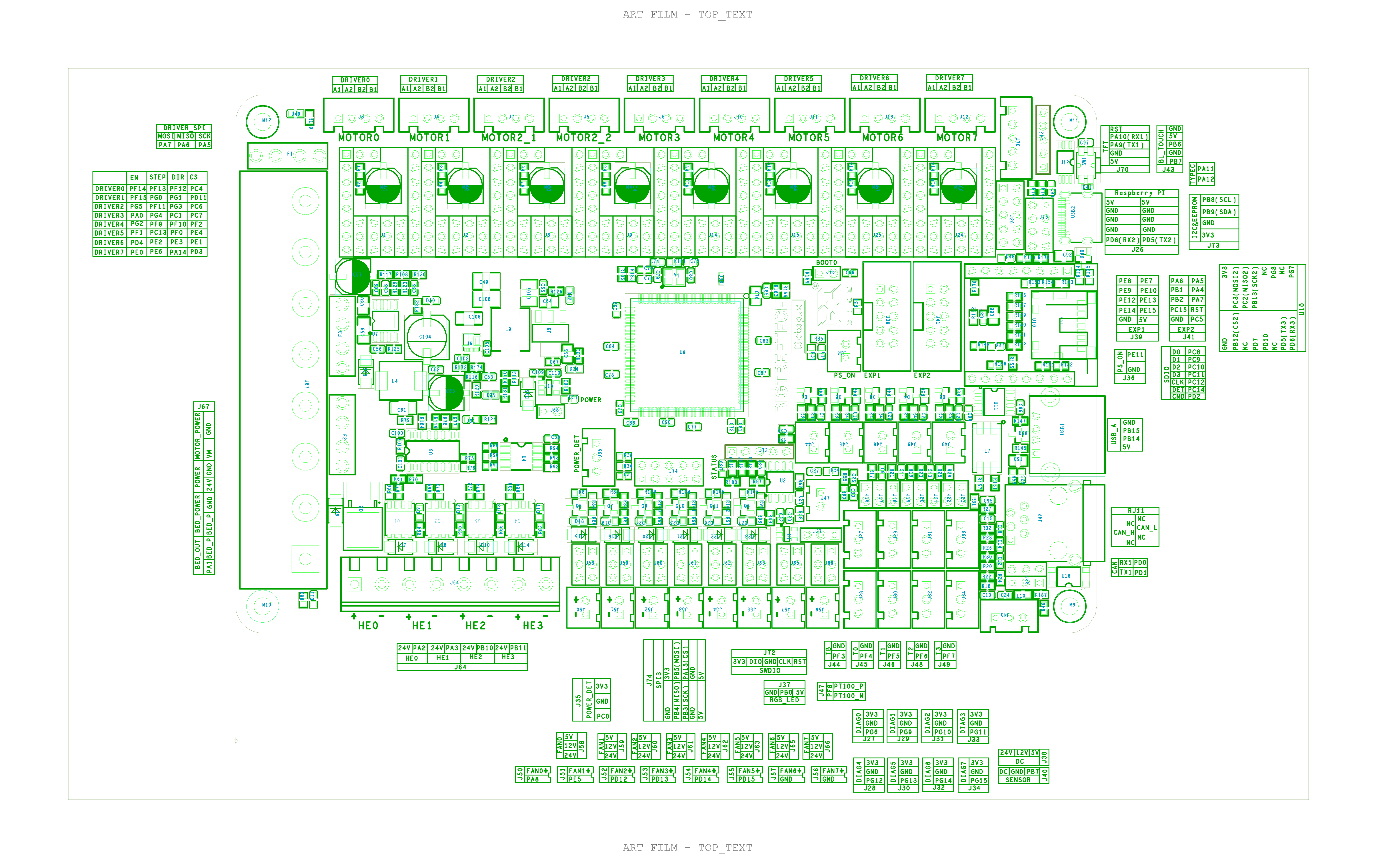
Bigtreetech Octopus 1.1 board
The wifi connector is for BTT WIFI module (16 pins)
|
|
| Board pins voltage |
3.3v |
| Board firmware |
Marlin |
| Board configuration note |
Enable second serial port (3) in the marlin configuration file |
| ESP3D configuration note |
Raw serial, no SD |
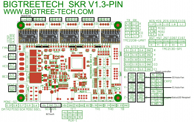
Bigtreetech skr board
Use the AUX1 or TFT connector
|
|
| Board pins voltage |
3.3v |
| Board firmware |
Marlin |
| Board configuration note |
Enable second serial port in the marlin configuration file |
| ESP3D configuration note |
Raw serial, no SD |
Bigtreetech skr mini board
This board is from Bigtreetech and went through various hardware revisions; all of them still feature a TFT pin header which is where you can tap the TX and RX needed. The wiring below is made with a 1.2 board, but the same applies for the other revisions as well; if you need the exact schematic for your mainboard version, you can check Bigtreetech’s github repository.
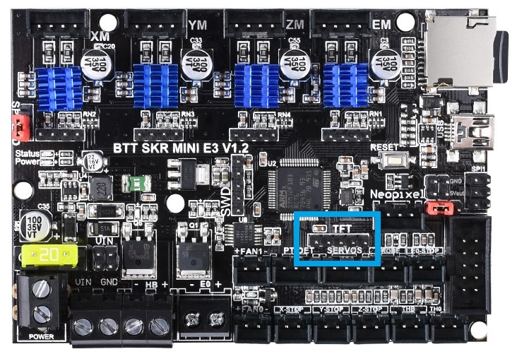
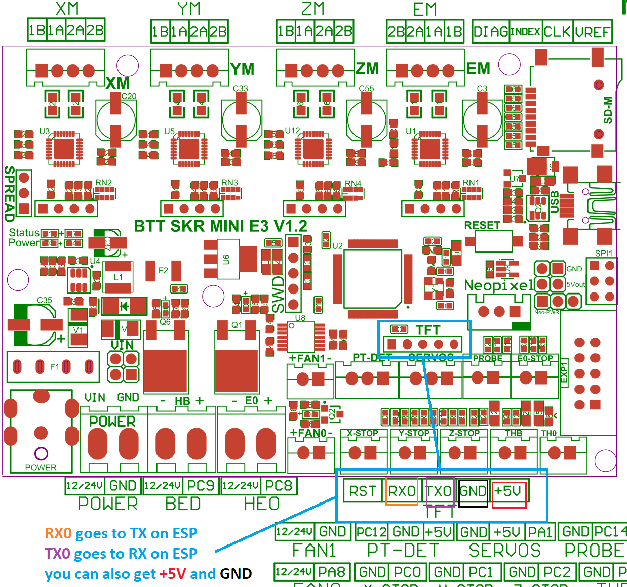
The TFT connector is labeled on the board; you can use dupont connectors for the wiring job, no soldering skills needed as long as your ESP comes with pre soldered headers.
Note: the TFT connector provides 5V DC, so be sure to provide them on the correct ESP pin.
|
|
| Board pins voltage |
3.3v |
| Board firmware |
Marlin |
| Board configuration note |
Enable second serial port in the marlin configuration file |
| ESP3D configuration note |
Raw serial, no SD |
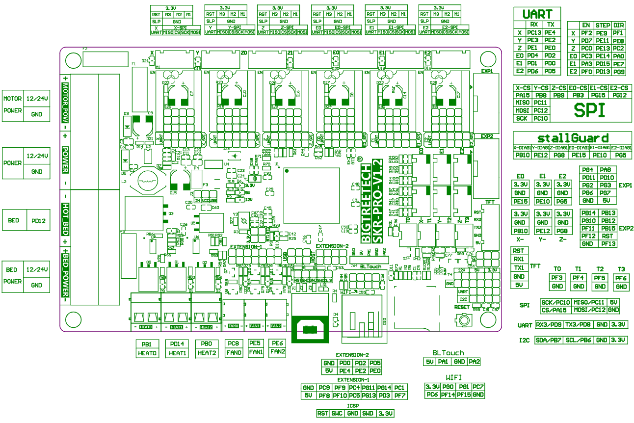
Bigtreetech skr pro board
This board has ESP01 socket available, so you can use the ESP01 module (or equivalent) directly.
|
|
| Board pins voltage |
3.3v |
| Board firmware |
Marlin |
| Board configuration note |
Enable second serial port in the marlin configuration file |
| ESP3D configuration note |
Raw serial, no SD |
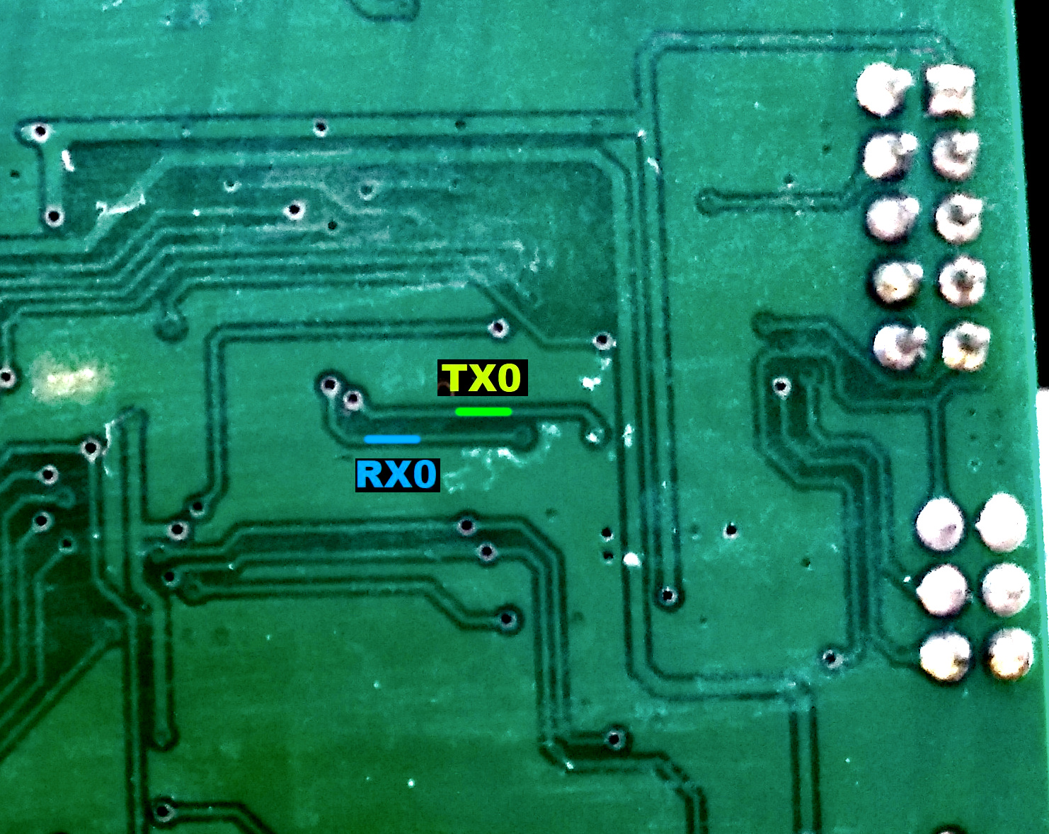
Creality CR10 Ender 3 board
For the Sanguino based CR-10 and Ender printers you will need to solder to any of the via circled (can also be done in the backside of board), or to the legs of the Arduino or ftdi. Connect TX from the board to RX of Wemos D1 mini and RX from board to TX of Wemos D1 mini. 5v and GND are located in the six pin header next to the LCD connector.
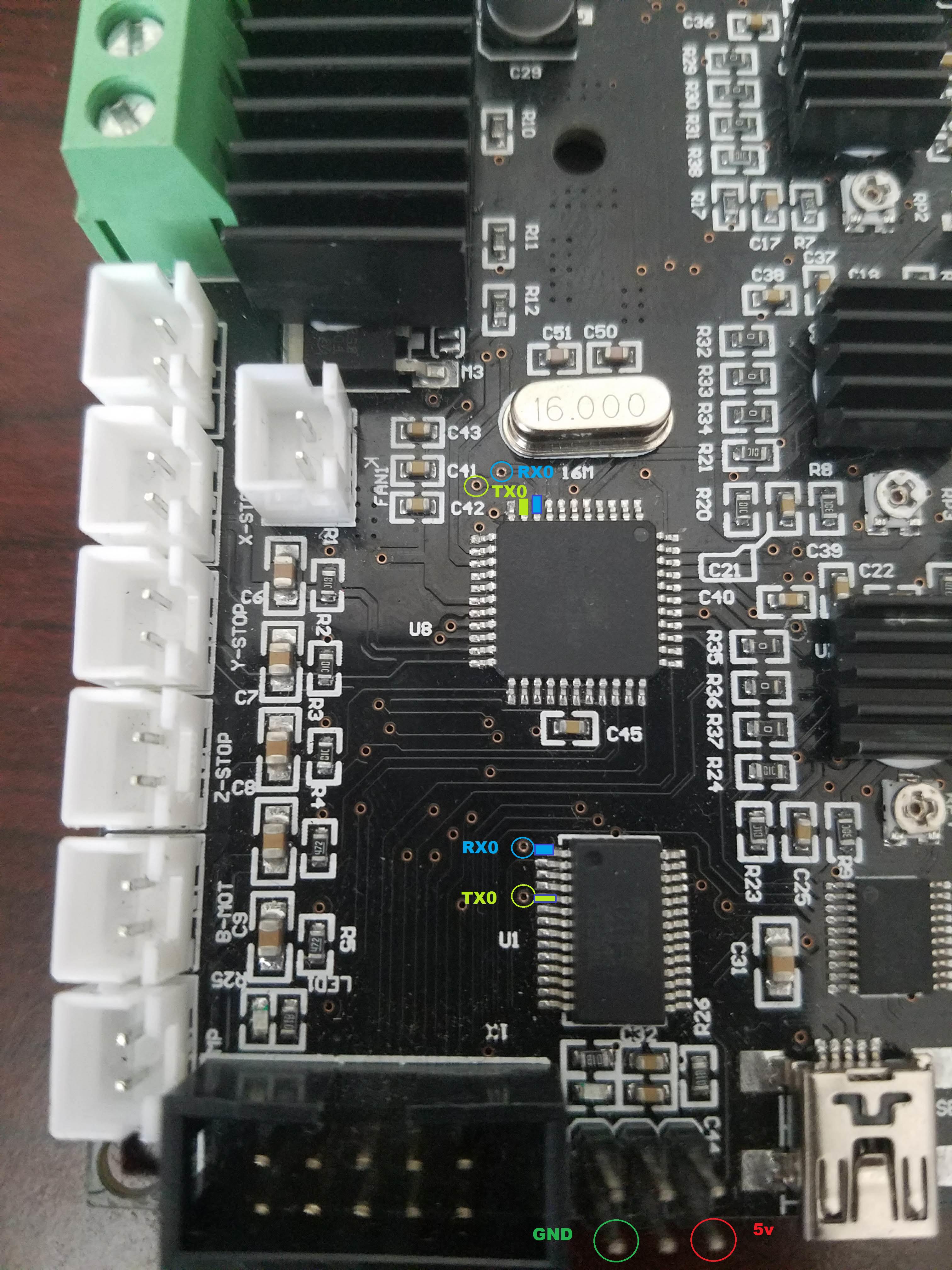
Since soldering might be difficult because the solder points are so close to each other, another option is to scrape off the insulation from the traces on the backside and solder there. Be extra careful not to scrape the surrounding ground plane. You need suitable fine scraping tools for this. The picture below shows an Ender-2 PCB.
|
|
| Board pins voltage |
5v |
| Board firmware |
Marlin |
| Board configuration note |
None, it use same serial as USB port so don’t use both together |
| ESP3D configuration note |
Raw serial, no SD |
Creality Ender 4 board
You will need to solder to small circle, or to the legs of the ATmega2560 (RXD0 pin 2, TXD0 pin 3)
|
|
| Board pins voltage |
5v |
| Board firmware |
Marlin |
| Board configuration note |
None, it use same serial as USB port so don’t use both together |
| ESP3D configuration note |
Raw serial, no SD |
MKS GEN v1.2 to 1.4 board
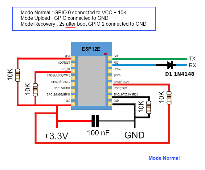
An ESP12E with the standard schematics, the two resistor connected to the RX pin are substituted by a 1N4148 diode, like in the Adafruit Huzzah board.
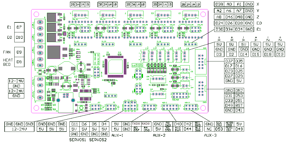
ESP12E is connected to the AUX1
ESP12E RX is connected to the pin NEAR GND of the upper row (Marked TXD on pinout.)
ESP12E TX is connected to the adiacent pin at the end of the upper row (Marked RXD on pinout.)
|
|
| Board pins voltage |
5v |
| Board firmware |
Marlin |
| Board configuration note |
None, it use same serial as USB port so don’t use both together |
| ESP3D configuration note |
Raw serial, no SD |
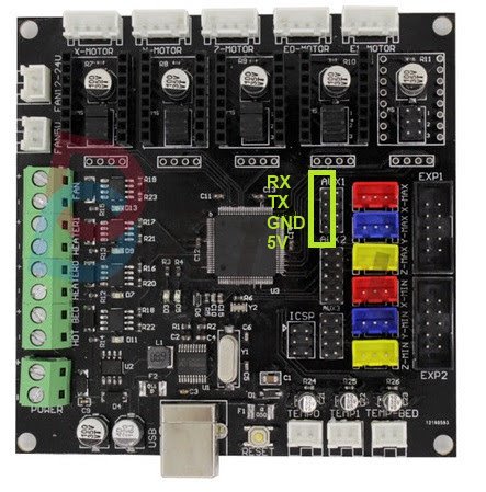
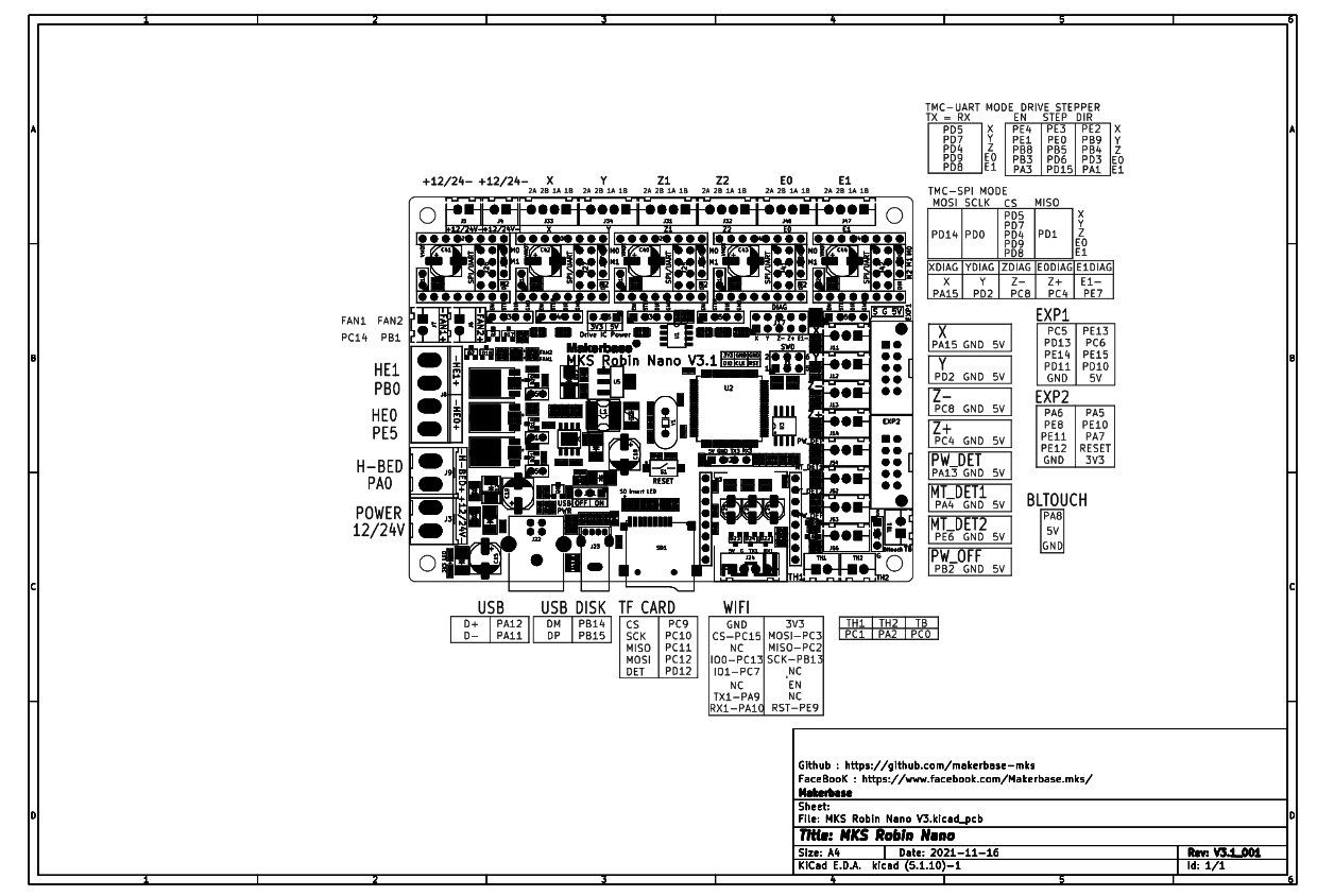
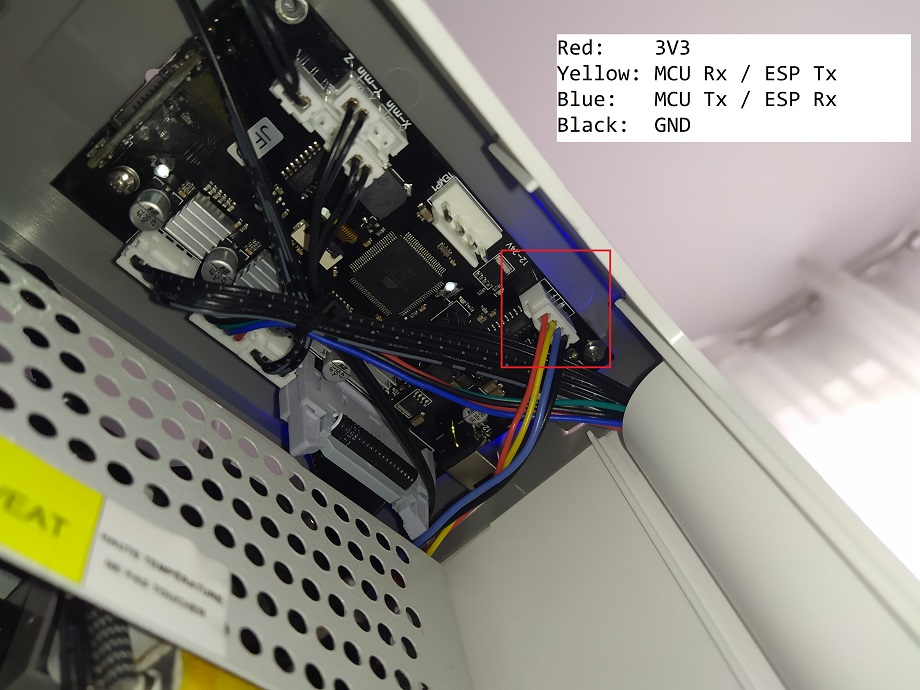
MKS Robin Nano board
This board has a socket for MKS WiFi module (16 pins)
|
|
| Board pins voltage |
3.3v |
| Board firmware |
Marlin |
| Board configuration note |
Enable MKS UI to be able to use MKS protocol |
| ESP3D configuration note |
MKS serial, no SD |
alternative solution using raw serial:
|
|
| Board configuration note |
Enable second serial port in firmware configuration |
| ESP3D configuration note |
Raw serial, no SD |
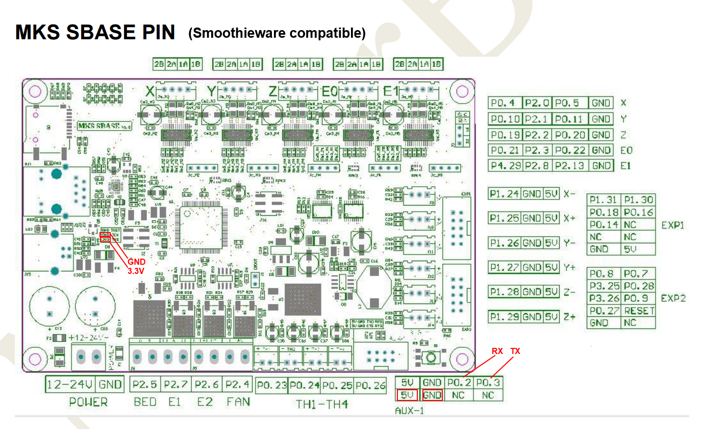
MKS SBase board
This board is smoothieware compatible, you need to connect ESP board to AUX1
|
|
| Board pins voltage |
3.3v |
| Board firmware |
Smoothieware |
| Board configuration note |
Enable second serial port in the config.txt |
| ESP3D configuration note |
Raw serial, no SD |
RADDS/Due
|
|
| Board pins voltage |
3.3v |
| Board firmware |
Marlin |
| Board configuration note |
Enable second serial port in the marlin configuration file |
| ESP3D configuration note |
Raw serial, no SD |
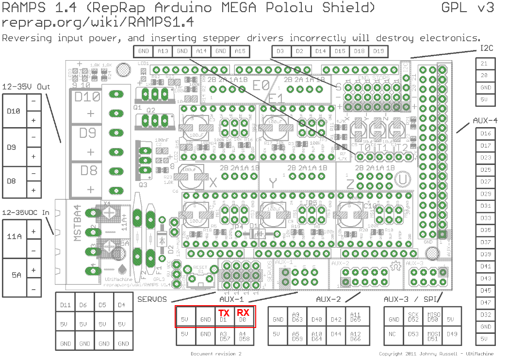
Ramps / Mega
Ramps 1.4 can be used on Arduino Mega (repetier/marlin) and Re-ARM for ramps boards (smoothieware/marlin)

|
|
| Board pins voltage |
5v |
| Board firmware |
Marlin |
| Board configuration note |
None, it use same serial as USB port so don’t use both together |
| ESP3D configuration note |
Raw serial, no SD |
Ramps / re-Arm
Re-ARM for ramps boards (smoothieware/marlin)
Alternative pins on Re-ARM (J4/UART port)
|
|
| Board pins voltage |
3.3v |
| Board firmware |
Marlin & Smoothieware |
| Board configuration note |
Enable second serial port in the formware configuration |
| ESP3D configuration note |
Raw serial, no SD |
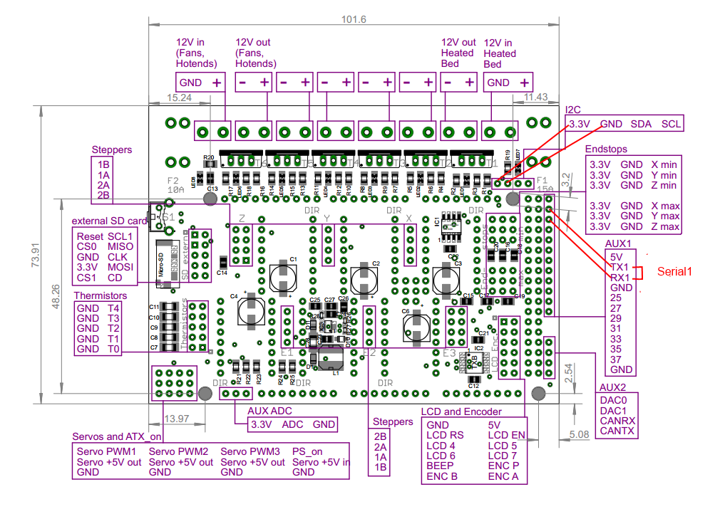
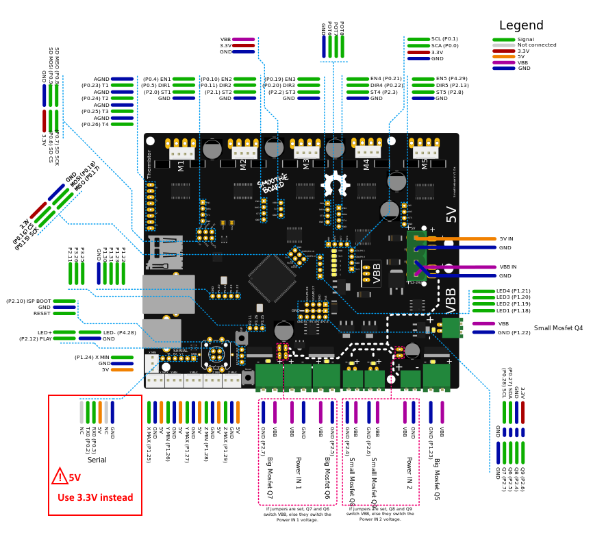
Smoothieboard
|
|
| Board pins voltage |
3.3v |
| Board firmware |
Smoothieware |
| Board configuration note |
Enable second serial port in the config.txt |
| ESP3D configuration note |
Raw serial, no SD |
Bigtreetech skr board
This printer is also brand labelled as Monoprice MP cadet 3D printer
|
|
| Board pins voltage |
5v |
| Board firmware |
Marlin |
| Board configuration note |
Enable second serial port (3) in firmware configuration file |
| ESP3D configuration note |
Raw serial, no SD |
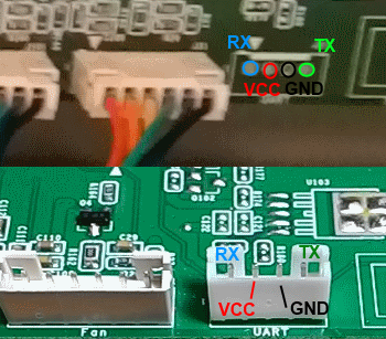
Davinci 1.0/2.0 board
The board is a due based and has a serial port available on the backside of the board. The serial port is a 4 pin header

|
|
| Board pins voltage |
3.3v |
| Board firmware |
Repetier for Davinci |
| Board configuration note |
Enable wifi in the firmware configuration file |
| ESP3D configuration note |
Raw serial, no SD |
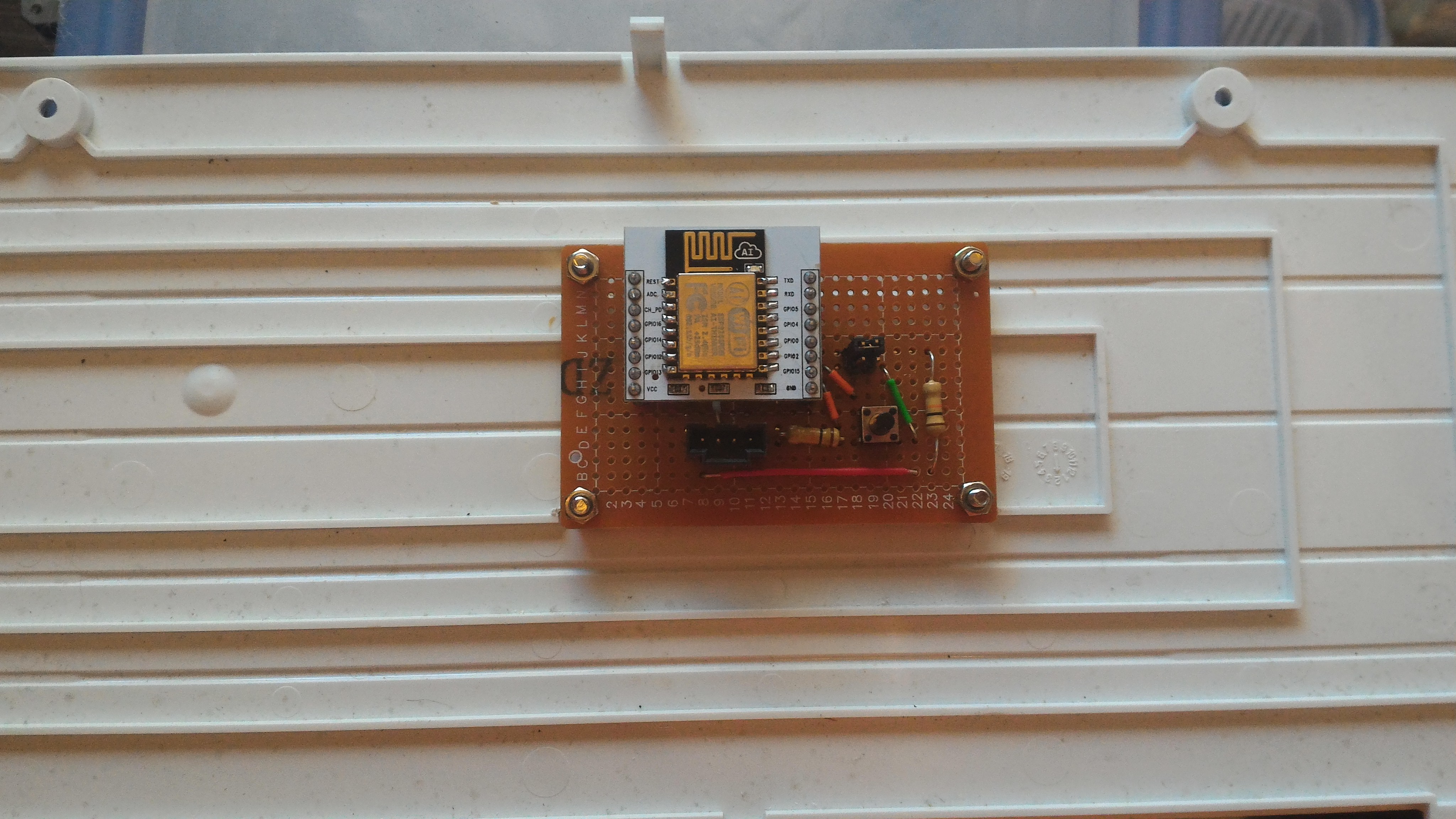
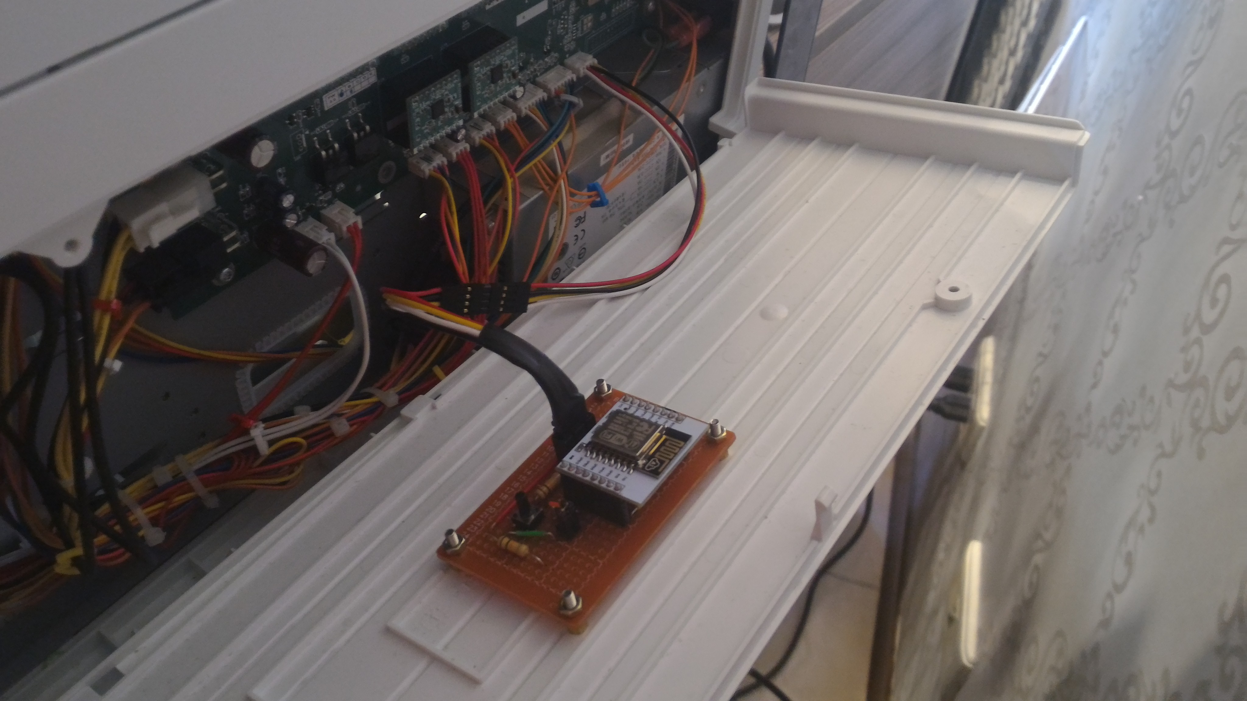
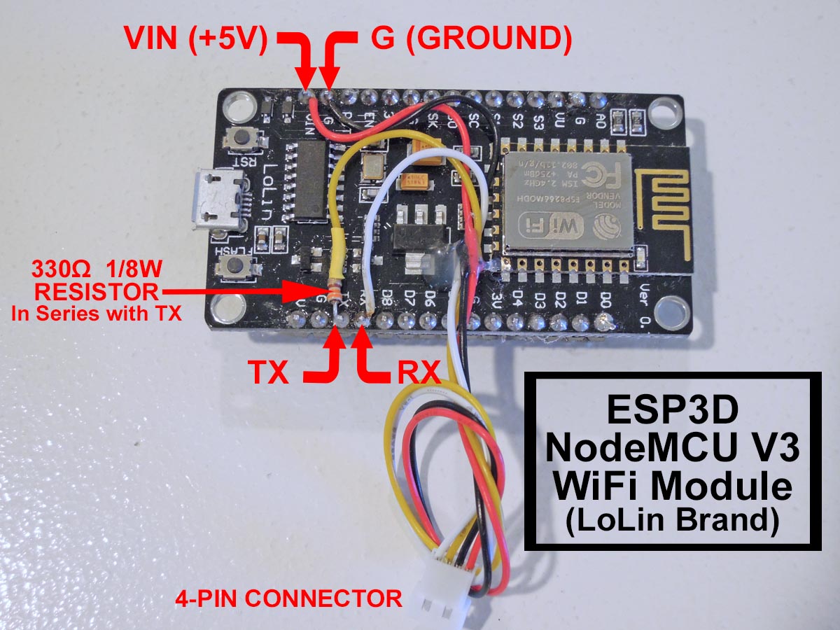
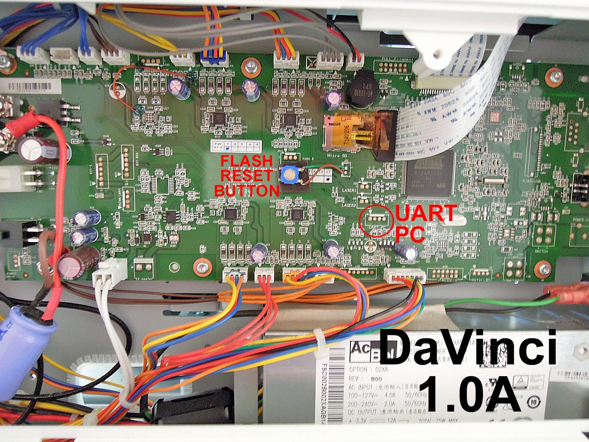
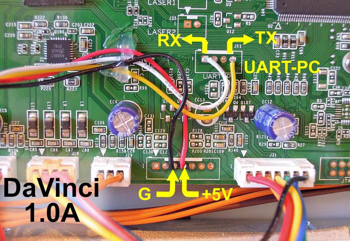
Davinci 1.0A board
It is a due based board and has a serial port available on the backside of the board. The serial port is a 4 pin header.
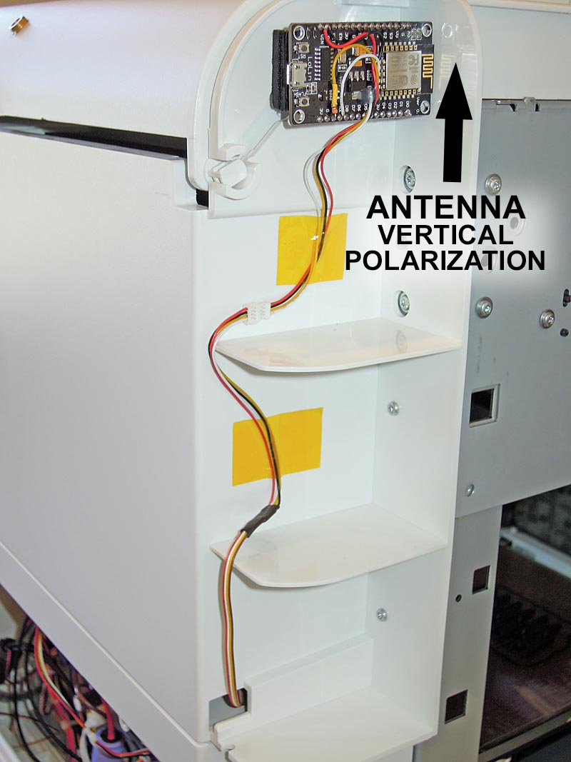
Alternate Module placement for increased WiFi range (outside metal chassis, antenna has vertical polarization)
|
|
| Board pins voltage |
3.3v |
| Board firmware |
Repetier for Davinci |
| Board configuration note |
Enable wifi in the firmware configuration file |
| ESP3D configuration note |
Raw serial, no SD |