Anet boards up to v1.5 and 1.7
Anet boards up to v1.5
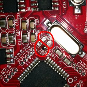
- Step 1
You will have to unsolder the resistors R52 and R53 – they are zero ohm resistors, and serve no other purpose than connecting the atmega chip directly to the onboard USB to UART converter (the CH340 chip). Do it VERY careful – you don’t want to damage your board. If you don’t feel confident – don’t do it.
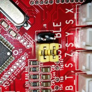
- Step 2
Prepare the printer’s motherboard. It requires a simple modification, that does not interfere with it’s operation afterwards – just solder 3 pin x 2 row male header on J8, and add 2 jumpers (or jumper wires) as shown on the picture:
- Step 3
Connect the ESP to J3 repsecting pinout
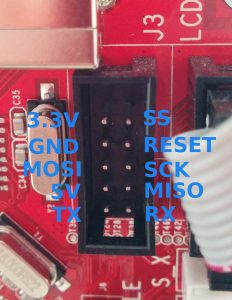
Pinout
| ESP | J3 |
|---|---|
| Tx | Rx |
| Rx | Tx |
| GND | GND |
| VCC | 3.3V |
| CH_PD | 3.3V |
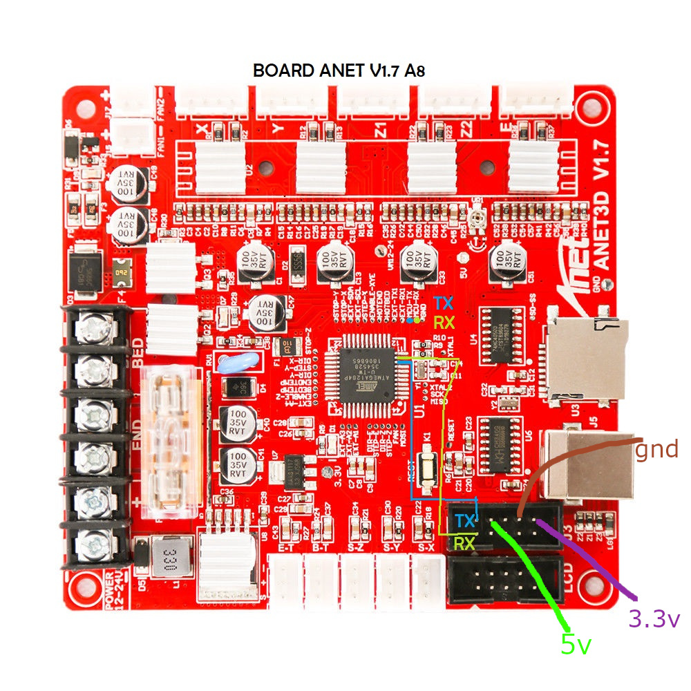
Anet boards v1.7
Unlike older boards this board does not require you to remove any resistors.
You will have to solder two wires from number 9 and number 10 its recommender to connect these to pin 1 and 2 of J3 connector.
| Board pins voltage | 5V |
| Board firmware | Marlin |
| Board configuration note | None, it use same serial as USB port so don’t use both together |
| ESP3D configuration note | Raw serial, no SD |