Version 1.X

This version is the development version, features can change anytime, feedback, PR and suggestions are welcome.

Firmware should work with the following firmwares:

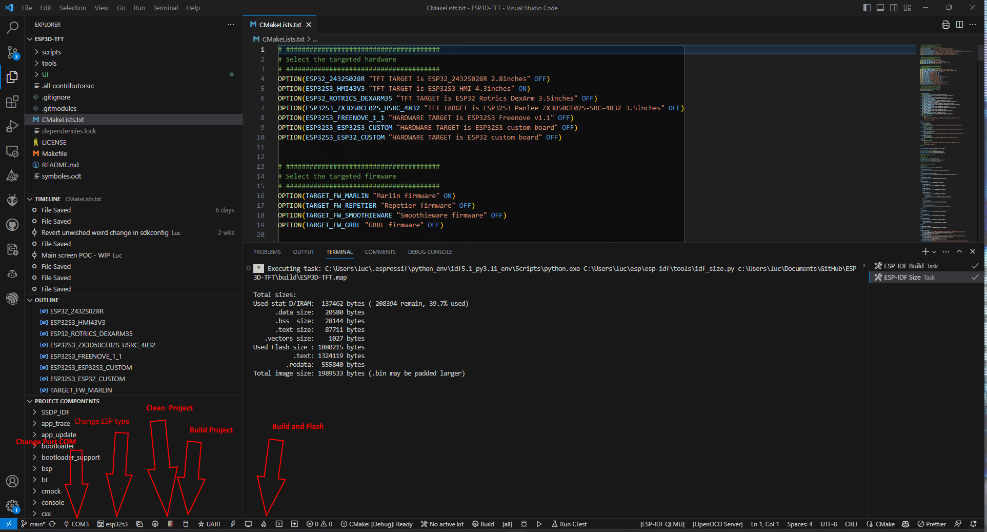
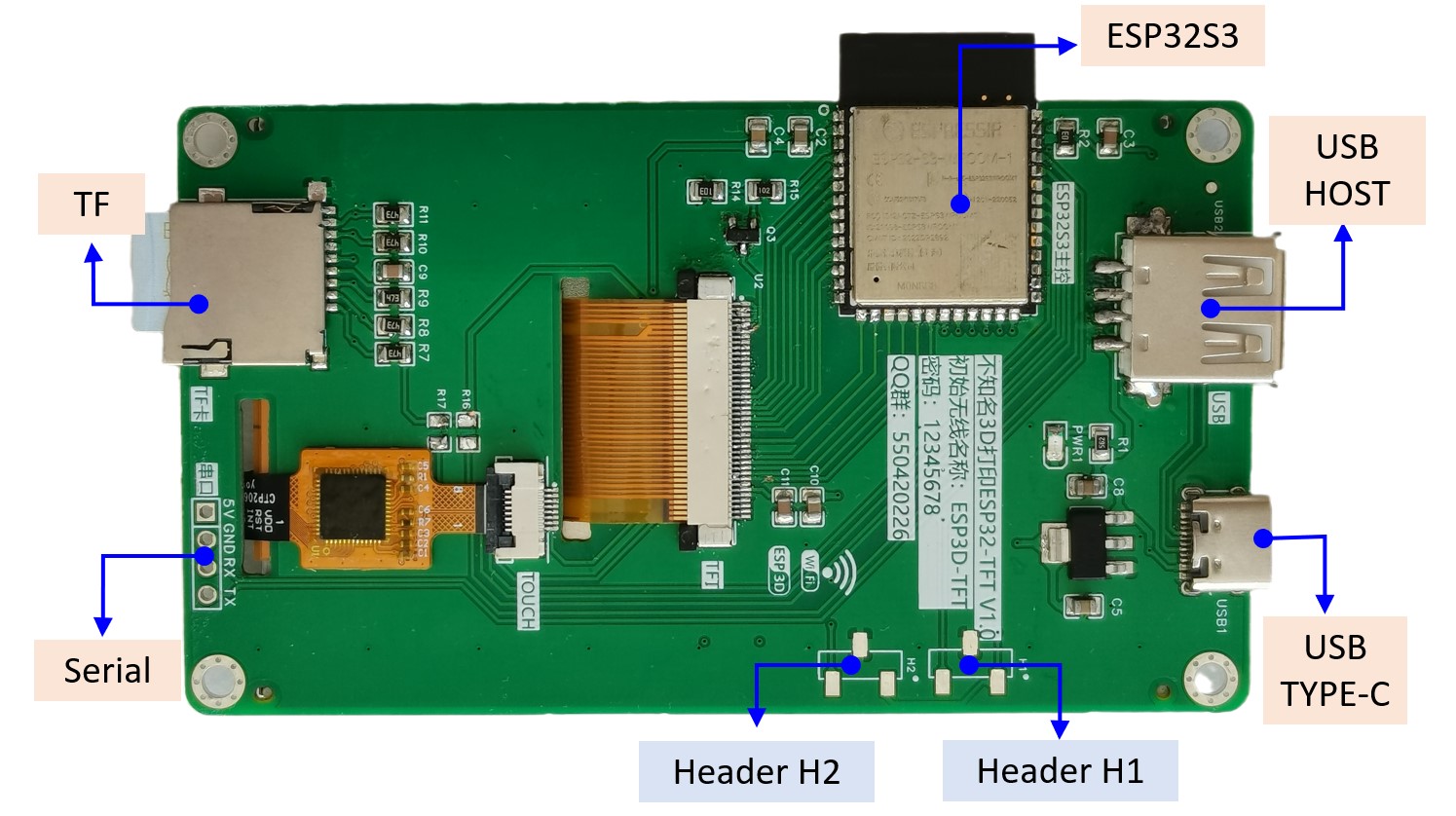
The communication between ESP board and target board is done by serial or by USB depending of ESP32 board.

The firmware must be used with ESP3D-WEBUI 3.X

Estimated planning

%%{init:{"theme":"default"}}%% gantt dateFormat YYYY-MM-DD title ESP3D-TFT Planning section Code Study IDF FrameWork Study :done, des1, 2022-08-24,2022-09-05 Code project definition :done, des2, 2022-09-06, 2022-09-16 section Code implementation Drivers implementation :done, des3, 2022-09-16, 2022-10-06 Serial implementation :done, des4, 2022-10-07, 2022-10-12 ESP3D Commands API :done, des5, 2022-10-13, 2022-10-23 Filesystem API :done, des6, 2022-10-24, 2022-10-27 Network implementation :done, des7, 2022-10-28, 2022-11-03 SD API :done, des8, 2022-11-04, 2022-11-06 HTTP Server :done, des9, 2022-11-07, 2022-12-04 WebSocket Server code base :done, des10, 2022-12-04, 2022-12-05 Tests and Bug fixes :done, des11, 2022-12-05, 2022-12-11 Update feature :done, des12, 2022-12-11, 2022-12-12 
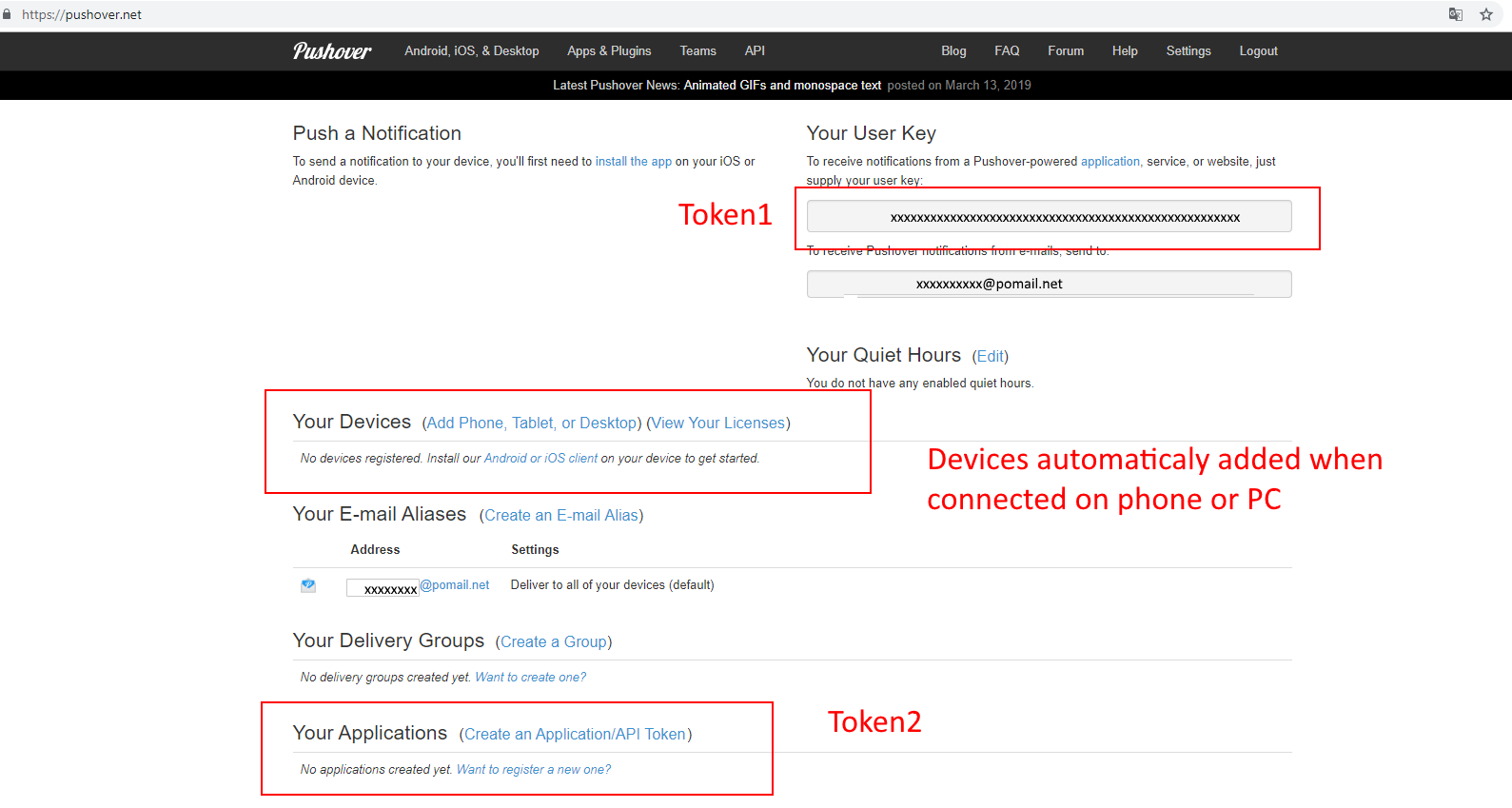
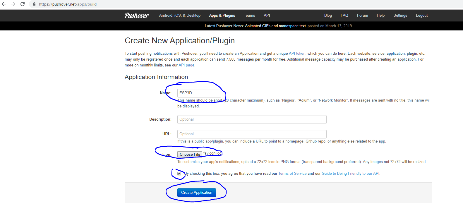
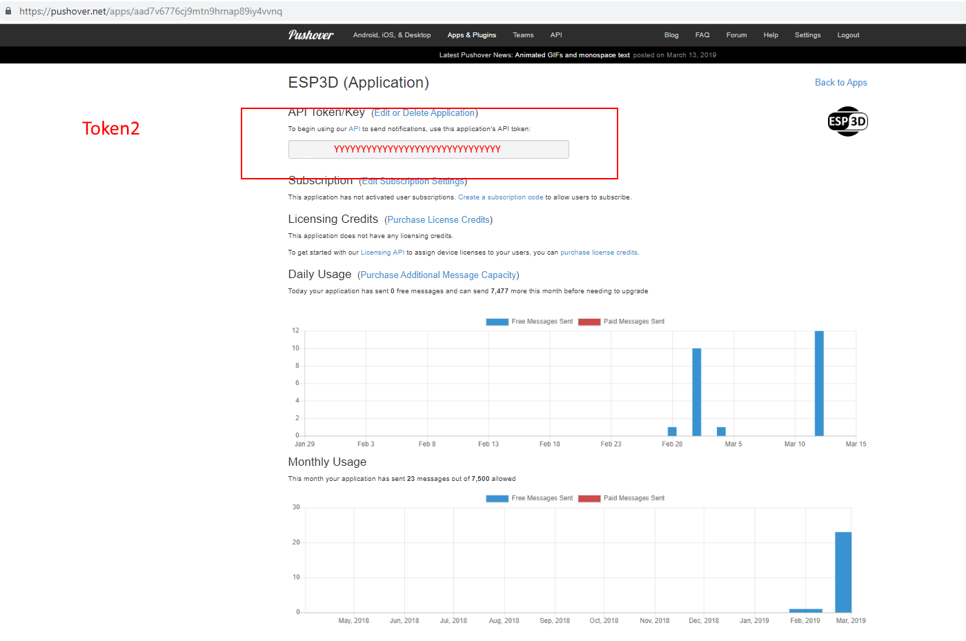
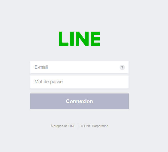
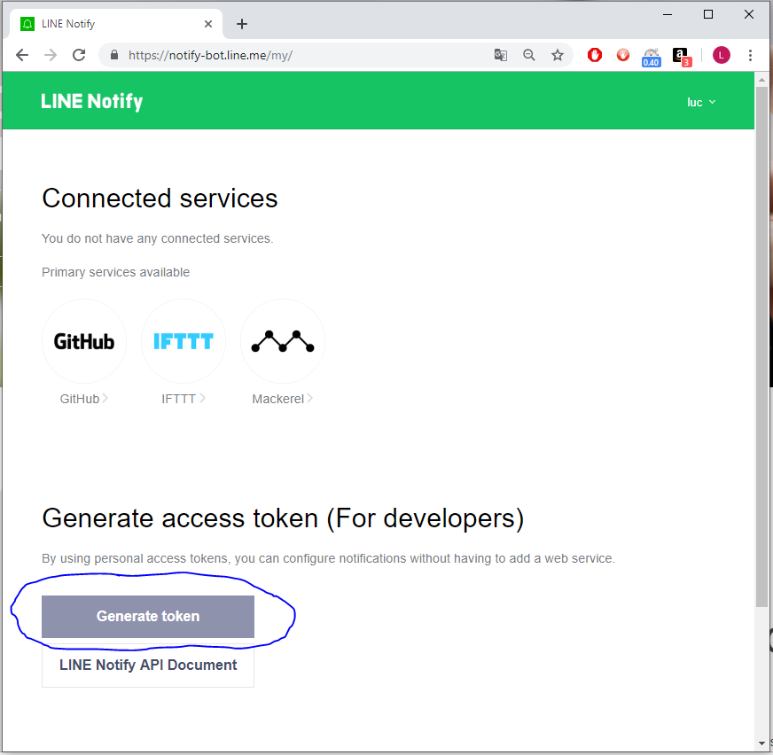
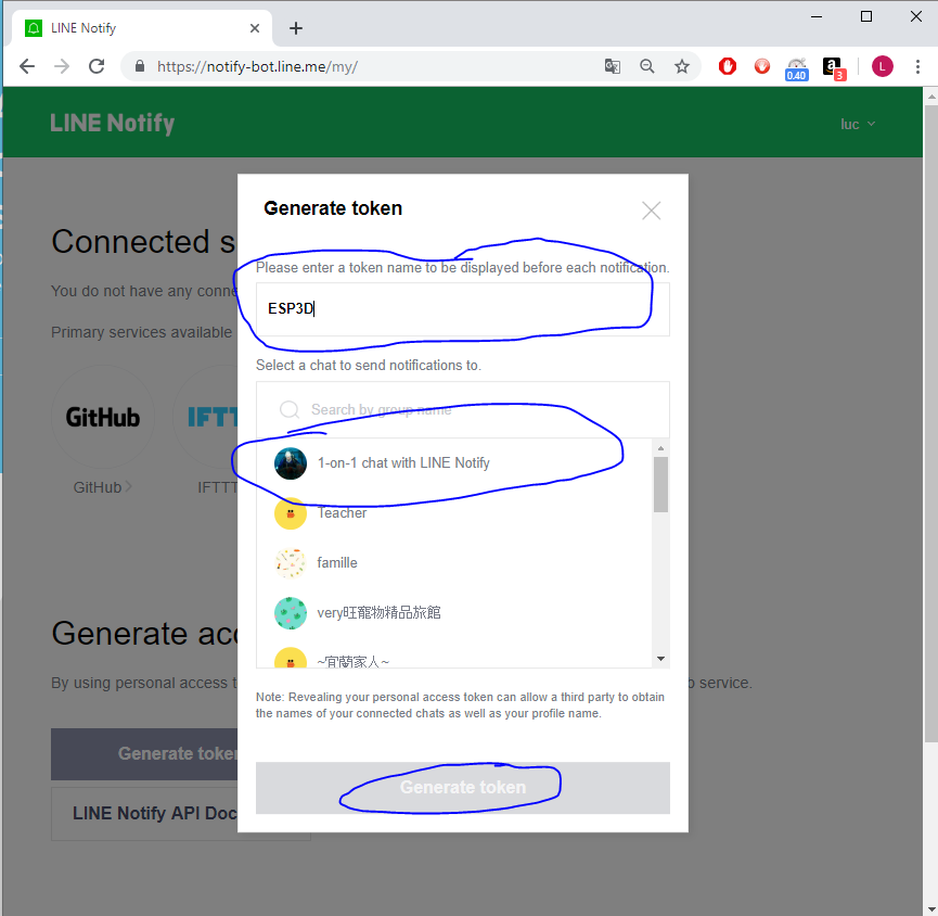
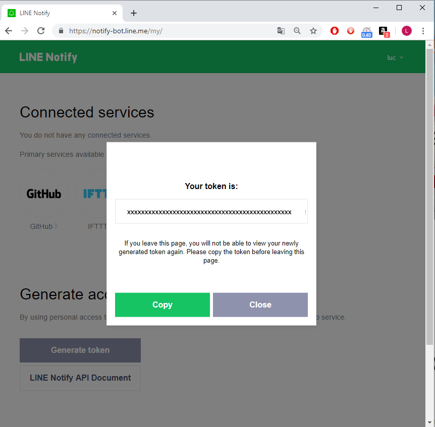
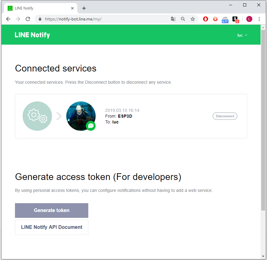
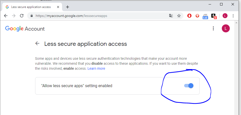
Notifications feature :done, des13, 2022-12-13, 2022-12-19 mDNS feature :done, des14, 2022-12-19, 2022-12-20 SSDP feature :done, des15, 2022-12-19, 2022-12-30 Telnet server feature :done, des16, 2022-12-31, 2023-01-07 Tests and Bug fixes :done, des17, 2022-12-31, 2023-01-15 USB Host feature :done, des18, 2023-01-16, 2023-01-18 Build-CI implementation :done, des19, 2023-01-18, 2023-01-22 Authentication implementation :done, des20, 2023-01-23, 2023-02-12 esp3d.io setup :done, des21, 2023-02-13, 2023-02-26 Tests and Bug fixes :done, des22, 2023-02-26, 2023-02-27 Streaming Host :active, des23, 2023-02-27, 60d TFT UI definition : des24, after des23, 7d TFT UI mockup : des25, after des24, 7d TFT UI implementation : des26, after des25, 60d Tests and Bug fixes : des27, after des26, 7d WebDAV implementation : des28, after des27, 14d Bluetooth implementation : des29, after des28, 7d Buzzer support : des30, after des29, 7d Pins control support : des31, after des30, 7d Auto script support at start : des32, after des31, 7d

If any error or need any addition,
please let me know by opening a ticket here
or submit a fix by PR or use the edit button on top menu

Subsections of Version 1.X

Features

The V3.X features are :

  • Embedded maintenance page (terminal / local FS update / ESP3D Firmware update)
  • WebUI support
  • ESP32 / ESP32-S3 support
  • Wifi
  • Raw TCP / serial bridge support (light telnet)
  • Websocket / serial bridge support
  • Serial / Serial bridge support
  • Bluetooth Serial bridge support (when BT supported)
  • Serial commands configurations
  • Authentication support (admin / user)
  • WebDav support
  • Local FS support:
    • Little FS
  • SD support(Direct connection)
    • File format
      • Native SPI
      • Native SDIO
  • USB Host support
  • Global FS under Webdav : SD + Local FS in same directory
  • Buzzer support
  • Pins control by commands
  • Time synchronization support (manual / internet server)
  • Notifications support
    • WebUI
    • TFT/OLED
    • Email
    • Line
    • Telegram
    • PushOver
    • IFTTT
  • Auto script support at start
  • Host GCODE stream for macros hosted on local FS (Work in Progress)
  • Update
    • ESP3D configuration using ini file on SD
    • ESP3D update using binary file on SD
    • OTA support
    • Update by WebUI

If any error or need any addition,
please let me know by opening a ticket here
or submit a fix by PR or use the edit button on top menu

Installation

Download the project

Using git

  • Clone repository
    git clone https://github.com/luc-github/ESP3D-TFT.git ESP3D-TFT
  • Go to the project
    cd ESP3D-TFT
  • Update the project submodules
    git submodule update --init --recursive
Note

If you have limited network access and have issue to connect to GitHub, it is recommended to use dev sidecar software.

Using release package

Not ready yet, please be patient

Setup your development environment

Download and install VSCode

Install the espressif vscode extension

The espressif extension can be installed using the extension manager.

Please follow the official tutorial

You can also install ESP-IDF offline .Especially suitable for people with slow download speeds.

  • Download installer.
  • Installing the installer.

Install the CMake extension and CMake Tools extension in vscode

Cmake can automatically download the components required for ESP3D, such as camera and USB host.

Configure the extension

  • Select : View->Command palette
  • Type : configure esp

Currently ESP3D-TFT use the released version 5.1 of the IDF

If you install ESP-IDF offline, you need to select “UseExitSetup”

image image

Then select the ESP IDF installation path

Open ESP3D-TFT project

  • Go to file and select open folder where project is located

Configure the CMakeLists.txt

Select the target according the hardware


# #######################################
# Select the targeted hardware
# #######################################

# With TFT:
OPTION(ESP32S3_HMI43V3 "TFT TARGET is ESP32S3 HMI 4.3inches" OFF)
OPTION(ESP32_ROTRICS_DEXARM35 "TFT TARGET is ESP32 Rotrics DexArm 3.5inches" OFF)
OPTION(ESP32S3_ZX3D50CE02S_USRC_4832 "TFT TARGET is ESP32S3 Panlee ZX3D50CE02S-SRC-4832 3.5inches" ON)
OPTION(ESP32S3_BZM_TFT35_GT911 "TFT TARGET is ESP32S3 Panlee BZM 3.5inches" OFF)
OPTION(ESP32S3_8048S070C "TFT TARGET is ESP32S3_8048S070C - 7.0in. 800x480 (Capacitive)" OFF)
OPTION(ESP32S3_8048S050C "TFT TARGET is ESP32S3_8048S050C - 5.0in. 800x480 (Capacitive)" OFF)
OPTION(ESP32S3_8048S043C "TFT TARGET is ESP32S3_8048S043C - 4.3in. 800x480 (Capacitive)" OFF)
OPTION(ESP32S3_4827S043C "TFT TARGET is ESP32S3_4827S043C - 4.3in. 480x272 (Capacitive)" OFF)
OPTION(ESP32_3248S035C "TFT TARGET is ESP32_3248S035C - 3.5in. 480x320 (Capacitive)" OFF)
OPTION(ESP32_3248S035R "TFT TARGET is ESP32_3248S035R - 3.5in. 480x320 (Resistive)" OFF)
OPTION(ESP32_2432S028R "TFT TARGET is ESP32_2432S028R - 2.8in. 320x240 (Resistive)" OFF)

# Without TFT:
OPTION(ESP32S3_FREENOVE_1_1 "HARDWARE TARGET is ESP32S3 Freenove v1.1" OFF)
OPTION(ESP32S3_CUSTOM "HARDWARE TARGET is ESP32S3 custom board" OFF)
OPTION(ESP32_CUSTOM "HARDWARE TARGET is ESP32 custom board" OFF)


# #######################################
# Optionally: Select hardware mods applied
# #######################################
#only for ESP32S3_8048S070C OR ESP32S3_8048S050C OR ESP32S3_8048S043C OR ESP32S3_4827S043C OR ESP32_3248S035C
OPTION(HARDWARE_MOD_GT911_INT "Hardware Mod: GT911 INT pin" OFF)

#Only for ESP32_3248S035C OR ESP32_3248S035R OR ESP32_2432S028R
# 4MB Flash, no PSRAM by default
OPTION(HARDWARE_MOD_8MB_FLASH "Hardware Mod: 8MB Flash Upgrade" OFF)
OPTION(HARDWARE_MOD_16MB_FLASH "Hardware Mod: 16MB Flash Upgrade" OFF)
OPTION(HARDWARE_MOD_EXT_PSRAM "Hardware Mod: External PSRAM" OFF)


# #######################################
# Select the targeted firmware
# #######################################
OPTION(TARGET_FW_MARLIN "Marlin firmware" ON)
OPTION(TARGET_FW_REPETIER "Repetier firmware" OFF)
OPTION(TARGET_FW_SMOOTHIEWARE "Smoothieware firmware" OFF)
OPTION(TARGET_FW_GRBL "GRBL firmware" OFF)


# #######################################
# Select the Features
# #######################################
OPTION(ESP3D_AUTHENTICATION "Authentication on all clients" OFF)
OPTION(DISABLE_SERIAL_AUTHENTICATION "Disable Serial Authentication" ON)
OPTION(TIME_SERVICE  "Time service" ON)
OPTION(SSDP_SERVICE "SSDP service" ON)
OPTION(MDNS_SERVICE "MDNS service" ON)
OPTION(WIFI_SERVICE "WiFi service" ON)
OPTION(BT_SERVICE "Bluetooth service" ON)
OPTION(WEB_SERVICES "Web Services http/websocket/webdav" ON)
OPTION(WEBDAV_SERVICES "WebDav Services" ON)
OPTION(TELNET_SERVICE "Telnet service" ON)
OPTION(WS_SERVICE "WebSocket data service" ON)
OPTION(TFT_UI_SERVICE "TFT UI service" ON)
OPTION(SD_CARD_SERVICE "SD card service" ON)
OPTION(NOTIFICATIONS_SERVICE "Notifications service" ON)
OPTION(UPDATE_SERVICE "Update service" ON)
OPTION(USE_FAT_INSTEAD_OF_LITTLEFS "Use FAT instead of LittleFS" OFF)

# #######################################
# Do not change anything below this line
# #######################################
cmake_minimum_required(VERSION 3.12.4)
set(CMAKE_CXX_STANDARD 20)

include (cmake/targets.cmake)

include($ENV{IDF_PATH}/tools/cmake/project.cmake)

include (cmake/features.cmake)

project(ESP3D-TFT
    VERSION 1.0
    DESCRIPTION "ESP3D TFT")

Clean / Compile / Flash

  • Select : View->Command palette
    • Type : ESP-IDF: (Clean / Build / Flash..)

or

  • Just use the bottom menu for all commands

image image

Note

Sometime the build button failed and you must delete the build directory manualy


If any error or need any addition,
please let me know by opening a ticket here
or submit a fix by PR or use the edit button on top menu

Documentation

The documentation section will help you on:


If any error or need any addition,
please let me know by opening a ticket here
or submit a fix by PR or use the edit button on top menu

Subsections of Documentation

ESP3D commands

Conventions

1 - Add space to separate parameters
2 - If parameter has space add \ in front of space to not be seen as separator
3 - json, json=YES, json=TRUE, json=1 are paremeters to switch output to json

By default output is plain text, to get json formated output add json or json=yes after main parameters.

The json format is:

{
    cmd:"<command id>", //the id of requested command
    status:"<ok/error>" //give if it is success or an failure
    data:"<response>" // response corresponding to answer in json format too
}

Commands

  • Show commands help
    [ESP]<command id> json=<no>

If any error or need any addition,
please let me know by opening a ticket here
or submit a fix by PR or use the edit button on top menu

Subsections of ESP3D commands

[ESP100]

Set / Display Station SSID

Input

[ESP100]<SSID> json=<no> pwd=<admin/user password>

  • json=no the output format
    can be in JSON or plain text

  • pwd= the admin password if authentication is enabled

  • SSID

    • if SSID is empty, it will display current SSID
    • if SSID is not empty, it will set the SSID

Output

  • In json format
{
   "cmd":"100",
   "status":"ok",
   "data":"esp3d"
}
  • cmd Id of requested command, should be 100
  • status status of command, should be ok
  • data content of response, here the SSID

If any error or need any addition,
please let me know by opening a ticket here
or submit a fix by PR or use the edit button on top menu

[ESP101]

Set Station Password

Input

[ESP101]<password> <NOPASSWORD> json=<no> pwd=<admin/user password>

  • json=no the output format
    can be in JSON or plain text

  • pwd= the admin password if authentication is enabled

  • password

    • if password is not empty, it will set the password
  • NOPASSWORD

    • if NOPASSWORD is present, it will remove the password
  • if password is empty and NOPASSWORD is not present, it will raise error: `Password not displayable``

Output

  • In json format:
{
   "cmd":"101",
   "status":"ok",
   "data":"ok"
}
  • cmd Id of requested command, should be 101
  • status status of command, should be ok
  • data content of response, here ok

if error :

  • in json format:
{
"cmd":"101",
"status":"error",
"data":"Password not displayable"
}
  • plain text:
error: Password not displayable

If any error or need any addition,
please let me know by opening a ticket here
or submit a fix by PR or use the edit button on top menu

[ESP102]

Set / Display Station IP mode

Input

[ESP102]<mode> json=<no> pwd=<admin/user password>

  • json=no the output format
    can be in JSON or plain text

  • pwd= the admin password if authentication is enabled

  • mode

    • if mode is empty, it will display current mode
    • if mode is not empty, it will set the setting mode: DHCP or STATIC

Output

  • In json format
{
   "cmd":"102",
   "status":"ok",
   "data":"DHCP"
}
  • cmd Id of requested command, should be 102
  • status status of command, should be ok
  • data content of response, here the mode

If any error or need any addition,
please let me know by opening a ticket here
or submit a fix by PR or use the edit button on top menu

[ESP103]

Set / Display Station IP address

Input

[ESP103]IP=<IP> MSK=<IP> GW=<IP> DNS=<IP> json=<no> pwd=<admin/user password>

  • json=no the output format
    can be in JSON or plain text

  • pwd= the admin password if authentication is enabled

  • IP

    • if IP is empty, it will display defined IP
    • if IP is not empty, it will set the IP
  • MSK

    • if MSK is empty, it will display defined Network Mask
    • if MSK is not empty, it will set the Network Mask
  • GW

    • if GW is empty, it will display defined Gateway
    • if GW is not empty, it will set the Gateway
  • DNS

    • if DNS is empty, it will display defined DNS
    • if DNS is not empty, it will set the DNS

Output

  • In json format
{
 "cmd": "103",
 "status": "ok",
 "data": {
  "ip": "192.168.0.1",
  "gw": "192.168.0.1",
  "msk": "255.255.255.0",
  "dns": "192.168.0.1"
 }
}
  • cmd Id of requested command, should be 103
  • status status of command, should be ok
  • data content of response, here the IP, GW, MSK and DNS

If any error or need any addition,
please let me know by opening a ticket here
or submit a fix by PR or use the edit button on top menu

[ESP104]

Set station fallback mode state at boot which can be BT, CONFIG, OFF

Input

[ESP104]<mode> json=<no> pwd=<admin/user password>

  • json=no the output format
    can be in JSON or plain text

  • pwd= the admin password if authentication is enabled

  • mode

    • if mode is empty, it will display current mode
    • if mode is not empty, it will set the setting mode: BT, CCONFIG or OFF

Output

  • In json format
{
   "cmd":"104",
   "status":"ok",
   "data":"OFF"
}
  • cmd Id of requested command, should be 104
  • status status of command, should be ok
  • data content of response, here the mode

If any error or need any addition,
please let me know by opening a ticket here
or submit a fix by PR or use the edit button on top menu

[ESP105]

Set / Display Access point SSID

Input

[ESP105]<SSID> json=<no> pwd=<admin/user password>

  • json=no the output format
    can be in JSON or plain text

  • pwd= the admin password if authentication is enabled

  • SSID

    • if SSID is empty, it will display current SSID
    • if SSID is not empty, it will set the SSID

Output

  • In json format
{
   "cmd":"105",
   "status":"ok",
   "data":"esp3d"
}
  • cmd Id of requested command, should be 105
  • status status of command, should be ok
  • data content of response, here the SSID

If any error or need any addition,
please let me know by opening a ticket here
or submit a fix by PR or use the edit button on top menu

[ESP106]

Set Access point password

Input

[ESP106]<password> <NOPASSWORD> json=<no> pwd=<admin/user password>

  • json=no the output format can be in JSON or plain text

  • pwd= the admin password if authentication is enabled

  • password

    • if password is not empty, it will set the password
  • NOPASSWORD

    • if NOPASSWORD is present, it will remove the password
  • if password is empty and NOPASSWORD is not present, it will raise error: `Password not displayable``

Output

  • In json format
{
   "cmd":"106",
   "status":"ok",
   "data":"ok"
}
  • cmd Id of requested command, should be 106
  • status status of command, should be ok
  • data content of response, here ok

If any error or need any addition,
please let me know by opening a ticket here
or submit a fix by PR or use the edit button on top menu

[ESP107]

Set / Display Access point IP value

Input

[ESP107]<IP> json=<no> pwd=<admin/user password>

  • json=no the output format can be in JSON or plain text

  • pwd= the admin password if authentication is enabled

  • IP

    • if IP is empty, it will display defined IP
    • if IP is not empty, it will set the IP

Output

  • In json format
{
   "cmd":"107",
   "status":"ok",
   "data":"192.168.0.1"
}
  • cmd Id of requested command, should be 107
  • status status of command, should be ok
  • data content of response, here the IP

If any error or need any addition,
please let me know by opening a ticket here
or submit a fix by PR or use the edit button on top menu

[ESP108]

Set / Display Access point channel value

Input

[ESP108]<channel> json=<no> pwd=<admin/user password>

  • json=no the output format can be in JSON or plain text

  • pwd= the admin password if authentication is enabled

  • channel

    • if channel is empty, it will display defined channel
    • if channel is not empty, it will set the channel

Output

  • In json format
{
   "cmd":"108",
   "status":"ok",
   "data":"1"
}
  • cmd Id of requested command, should be 108
  • status status of command, should be ok
  • data content of response, here the channel

If any error or need any addition,
please let me know by opening a ticket here
or submit a fix by PR or use the edit button on top menu

[ESP110]

Set / display radio state at boot which can be BT, STA, AP, CONFIG, OFF

Input

[ESP110]<mode> json=<no> pwd=<admin/user password>

  • json=no the output format can be in JSON or plain text

  • pwd= the admin password if authentication is enabled

  • mode

    • if mode is empty, it will display current mode
    • if mode is not empty, it will set the setting mode: BT, STA, AP, CONFIG or OFF

Output

  • In json format
{
   "cmd":"110",
   "status":"ok",
   "data":"OFF"
}
  • cmd Id of requested command, should be 110
  • status status of command, should be ok
  • data content of response, here the mode OFF

If any error or need any addition,
please let me know by opening a ticket here
or submit a fix by PR or use the edit button on top menu

[ESP111]

Display current IP

Input

[ESP111]<ALL> json=<no> pwd=<admin/user password>

  • json=no the output format can be in JSON or plain text

  • pwd= the admin password if authentication is enabled

  • ALL

    • it is set it will display IP, GW, MSK, DNS ip

Output

  • In json format
{
   "cmd":"111",
   "status":"ok",
   "data":"192.168.0.1"
}
  • cmd Id of requested command, should be 111
  • status status of command, should be ok
  • data content of response, here the IP

If any error or need any addition,
please let me know by opening a ticket here
or submit a fix by PR or use the edit button on top menu

[ESP112]

Set / Display Hostname

Input

[ESP112]<hostname> json=<no> pwd=<admin/user password>

  • json=no the output format can be in JSON or plain text

  • pwd= the admin password if authentication is enabled

  • hostname

    • if hostname is empty, it will display current hostname
    • if hostname is not empty, it will set the hostname

Output

  • In json format
{
   "cmd":"112",
   "status":"ok",
   "data":"esp3d"
}
  • cmd Id of requested command, should be 112
  • status status of command, should be ok
  • data content of response, here the hostname

If any error or need any addition,
please let me know by opening a ticket here
or submit a fix by PR or use the edit button on top menu

[ESP114]

Get/Set Boot radio state which can be ON, OFF

Input

[ESP114]<mode> json=<no> pwd=<admin/user password>

  • json=no the output format can be in JSON or plain text

  • pwd= the admin password if authentication is enabled

  • mode

    • if mode is empty, it will display current mode
    • if mode is not empty, it will set the setting mode: ON or OFF

Output

  • In json format
{
   "cmd":"114",
   "status":"ok",
   "data":"OFF"
}
  • cmd Id of requested command, should be 114
  • status status of command, should be ok
  • data content of response, here the mode

If any error or need any addition,
please let me know by opening a ticket here
or submit a fix by PR or use the edit button on top menu

[ESP115]

Get/Set immediate Network (WiFi/BT/Ethernet) state which can be ON, OFF

Input

[ESP115]<mode> json=<no> pwd=<admin/user password>

  • json=no the output format can be in JSON or plain text

  • pwd= the admin password if authentication is enabled

  • mode

    • if mode is empty, it will display current mode
    • if mode is not empty, it will set the setting mode: ON or OFF

Output

  • In json format
{
   "cmd":"115",
   "status":"ok",
   "data":"OFF"
}
  • cmd Id of requested command, should be 115
  • status status of command, should be ok
  • data content of response, here the mode

If any error or need any addition,
please let me know by opening a ticket here
or submit a fix by PR or use the edit button on top menu

[ESP120]

Get/Set HTTP state which can be ON, OFF

Input

[ESP120]<mode> json=<no> pwd=<admin/user password>

  • json=no the output format can be in JSON or plain text

  • pwd= the admin password if authentication is enabled

  • mode

    • if mode is empty, it will display current mode
    • if mode is not empty, it will set the setting mode: ON or OFF

Output

  • In json format
{
   "cmd":"120",
   "status":"ok",
   "data":"OFF"
}
  • cmd Id of requested command, should be 120
  • status status of command, should be ok
  • data content of response, here the mode

If any error or need any addition,
please let me know by opening a ticket here
or submit a fix by PR or use the edit button on top menu

[ESP121]

Get/Set HTTP port

Input

[ESP121]<port> json=<no> pwd=<admin/user password>

  • json=no the output format can be in JSON or plain text

  • pwd= the admin password if authentication is enabled

  • port

    • if port is empty, it will display current port
    • if port is not empty, it will set the port

Output

  • In json format
{
   "cmd":"121",
   "status":"ok",
   "data":"80"
}
  • cmd Id of requested command, should be 121
  • status status of command, should be ok
  • data content of response, here the port

If any error or need any addition,
please let me know by opening a ticket here
or submit a fix by PR or use the edit button on top menu

[ESP130]

Get/Set TELNET state which can be ON, OFF, CLOSE

Input

[ESP130]<mode> json=<no> pwd=<admin/user password>

  • json=no the output format can be in JSON or plain text

  • pwd= the admin password if authentication is enabled

  • mode

    • if mode is empty, it will display current mode
    • if mode is not empty, it will set the setting mode: ON, OFF or CLOSE

Output

  • In json format
{
   "cmd":"130",
   "status":"ok",
   "data":"OFF"
}
  • cmd Id of requested command, should be 130
  • status status of command, should be ok
  • data content of response, here the mode

If any error or need any addition,
please let me know by opening a ticket here
or submit a fix by PR or use the edit button on top menu

[ESP131]

Get/Set TELNET port

Input

[ESP131]<port> json=<no> pwd=<admin/user password>

  • json=no the output format can be in JSON or plain text

  • pwd= the admin password if authentication is enabled

  • port

    • if port is empty, it will display current port
    • if port is not empty, it will set the port

Output

  • In json format
{
   "cmd":"131",
   "status":"ok",
   "data":"23"
}
  • cmd Id of requested command, should be 131
  • status status of command, should be ok
  • data content of response, here the port

If any error or need any addition,
please let me know by opening a ticket here
or submit a fix by PR or use the edit button on top menu

[ESP140]

Sync / Set / Get current time

Input

[ESP140]<SYNC> <srv1=XXXXX> <srv2=XXXXX> <srv3=XXXXX> <tzone=+HH:SS> <ntp=YES/NO> <time=YYYY-MM-DDTHH:mm:ss> NOW json=<no> pwd=<admin password>

  • json=no the output format can be in JSON or plain text

  • pwd= the admin password if authentication is enabled

  • srv1 / srv2 / srv3

    • if srv1 / srv2 / srv3 are empty, it will display current NTP servers
    • if srv1 / srv2 / srv3 are not empty, it will set the NTP servers
  • tzone

    • if tzone is empty, it will display current time zone
    • if tzone is not empty, it will set the time zone
  • time

    • if time is empty, it will display current time
    • if time is not empty, it will set the time
  • ntp

    • if ntp is empty, it will display current NTP state
    • if ntp is not empty, it will set the NTP state
  • SYNC

    • if SYNC, it will restart NTP service to sync time
  • NOW

    • if NOW, it will display current time in ISO 8601 format with time zone

Output

  • In json format
{
   "cmd":"140",
   "status":"ok",
   "data":"2020-01-01T00:00:00 (+08:00)"
}
  • cmd Id of requested command, should be 140
  • status status of command, should be ok
  • data content of response, here the time

If any error or need any addition,
please let me know by opening a ticket here
or submit a fix by PR or use the edit button on top menu

[ESP160]

Get/Set WebSocket state which can be ON, OFF, CLOSE

Input

[ESP160]<mode> json=<no> pwd=<admin/user password>

  • json=no the output format can be in JSON or plain text

  • pwd= the admin password if authentication is enabled

  • mode

    • if mode is empty, it will display current mode
    • if mode is not empty, it will set the setting mode: ON, OFF or CLOSE

Output

  • In json format
{
   "cmd":"160",
   "status":"ok",
   "data":"OFF"
}
  • cmd Id of requested command, should be 160
  • status status of command, should be ok
  • data content of response, here the mode

If any error or need any addition,
please let me know by opening a ticket here
or submit a fix by PR or use the edit button on top menu

[ESP170]

Get /Set Camera command value / list all values in JSON/plain text

Input

[ESP170]<label=value> <json=no> pwd=<admin password>

  • json=no the output format can be in JSON or plain text

  • pwd= the admin password if authentication is enabled

  • label

    • if label is empty, it will display current value
    • if label is not empty, it will set the value

    label can be: light/framesize/quality/contrast/brightness/saturation/gainceiling/colorbar/awb/agc/aec/hmirror/vflip/awb_gain/agc_gain/aec_value/aec2/cw/bpc/wpc/raw_gma/lenc/special_effect/wb_mode/ae_level
    value depend on label

Output

  • In json format
{
   "cmd":"170",
   "status":"ok",
   "data":"ok"
}
  • cmd Id of requested command, should be 170
  • status status of command, should be ok | data content of response, here ok

Framesize

Framesize can be:

Value Description resolution
0 FRAMESIZE_96X96 96x96
1 FRAMESIZE_QQVGA 160x120
2 FRAMESIZE_QCIF 176x144
3 FRAMESIZE_HQVGA 240x176
4 FRAMESIZE_240X240 240x240
5 FRAMESIZE_QVGA 320x240
6 FRAMESIZE_CIF 400x296
7 FRAMESIZE_HVGA 480x320
8 FRAMESIZE_VGA 640x480
9 FRAMESIZE_SVGA 800x600
10 FRAMESIZE_XGA 1024x768
11 FRAMESIZE_HD 1280x720
12 FRAMESIZE_SXGA 1280x1024
13 FRAMESIZE_UXGA 1600x1200
14 FRAMESIZE_FHD 1920x1080
15 FRAMESIZE_P_HD 720x1280
16 FRAMESIZE_P_3MP 864x1536
17 FRAMESIZE_QXGA 2048x1536
18 FRAMESIZE_QHD 2560x1440
19 FRAMESIZE_WQXGA 2560x1600
20 FRAMESIZE_P_FHD 1080x1920
21 FRAMESIZE_QSXGA 2560x1920

If any error or need any addition,
please let me know by opening a ticket here
or submit a fix by PR or use the edit button on top menu

[ESP171]

Save frame to target path and filename (default target = today date, default name=timestamp.jpg)

Input

[ESP171]<json=no> path=<target path> filename=<target filename> pwd=<admin/user password>

  • json=no the output format can be in JSON or plain text

  • pwd= the admin password if authentication is enabled

  • path

    • if path is not empty, it will set the path
  • filename

    • if filename is not empty, it will set the filename

Output

  • In json format
{
   "cmd":"171",
   "status":"ok",
   "data":"Snapshot taken"
}
  • cmd Id of requested command, should be 171
  • status status of command, should be ok
  • data content of response, here Snapshot taken

If any error or need any addition,
please let me know by opening a ticket here
or submit a fix by PR or use the edit button on top menu

[ESP200]

Get/Set SD state

Input

[ESP200] json=<YES/NO> <RELEASESD> <REFRESH> pwd=<user/admin password>

  • json=no the output format can be in JSON or plain text

  • pwd= the admin password if authentication is enabled

    • RELEASESD

      • if RELEASESD is present, it will release SD card
    • REFRESH

      • if REFRESH is present, it will refresh SD card

Output

  • In json format
{
   "cmd":"200",
   "status":"ok",
   "data":"ok"
}

states can be : Busy. "Not available, ok, No SD card

  • cmd Id of requested command, should be 200
  • status status of command, should be ok
  • data content of response, here ok

If any error or need any addition,
please let me know by opening a ticket here
or submit a fix by PR or use the edit button on top menu

[ESP202]

Get/Set SD card Speed factor 1 2 4 6 8 16 32

Input

[ESP202]SPEED=<factor> json=<no> pwd=<admin password>

  • json=no the output format can be in JSON or plain text

  • pwd= the admin password if authentication is enabled

  • SPEED=

    • if factor is empty, it will display current factor
    • if factor is not empty, it will set the factor

Output

  • In json format
{
   "cmd":"202",
   "status":"ok",
   "data":"1"
}
  • cmd Id of requested command, should be 202
  • status status of command, should be ok
  • data content of response, here the current SPI factor

If any error or need any addition,
please let me know by opening a ticket here
or submit a fix by PR or use the edit button on top menu

[ESP210]

Get Sensor Value / type/Set Sensor type

Input

[ESP210]<type=NONE/xxx> <interval=XXX in millisec> json=<no> pwd=<admin password>

  • json=no the output format can be in JSON or plain text

  • pwd= the admin password if authentication is enabled

    • type

      • if type is empty, it will display current type
      • if type is not empty, it will set the type
    • interval

      • if interval is empty, it will display current interval
      • if interval is not empty, it will set the interval

Output

  • In json format
{
   "cmd":"210",
   "status":"ok",
   "data":"ok"
}
  • cmd Id of requested command, should be 210
  • status status of command, should be ok
  • data content of response, here ok

If any error or need any addition,
please let me know by opening a ticket here
or submit a fix by PR or use the edit button on top menu

[ESP214]

Output to esp screen status

Input

[ESP214]<Text> json=<no> pwd=<admin password>

  • json=no the output format can be in JSON or plain text

  • pwd= the admin password if authentication is enabled

  • Text

    • if Text is not empty, it will set the Text
    • if Text is empty, it will clear current Text

Output

  • In json format
{
   "cmd":"214",
   "status":"ok",
   "data":"ok"
}
  • cmd Id of requested command, should be 214
  • status status of command, should be ok
  • data content of response, here ok

If any error or need any addition,
please let me know by opening a ticket here
or submit a fix by PR or use the edit button on top menu

[ESP216]

Do Snapshot of current screen and save to SD card, need enable LV_USE_SNAPSHOT=1 in cmake\dev_tools.make

Input

[ESP216]<SNAP> json=<no> pwd=<admin/user password>

  • json=no the output format can be in JSON or plain text

  • pwd=<admin/user password> the admin password if authentication is enabled

  • SNAP

    • if SNAP is set, it will take a snapshot
    • if SNAP is not set, it will not take a snapshot

Output

  • In json format
{
   "cmd":"216",
   "status":"ok",
   "data":"ok"
}
  • cmd Id of requested command, should be 216
  • status status of command, should be ok
  • data content of response, here ok

Additionnaly a raw file named snapshot<timestamp>.raw will be saved in the SD card if the snapshot is enabled

The raw file can be converted to a png file using the script tools/imageconv/conv.py
e.g. python conv.py snapshot<timestamp>.raw will generate a file:
snapshot<timestamp>.raw.png


If any error or need any addition,
please let me know by opening a ticket here
or submit a fix by PR or use the edit button on top menu

[ESP220]

Get ESP3D pins definition

Input

[ESP220] json=<no> pwd=<admin password>

  • json=no the output format can be in JSON or plain text

  • pwd= the admin password if authentication is enabled

Output

  • In json format
{
 "cmd": "220",
 "status": "ok",
 "data": [
  {
   "id": "SD CS",
   "value": "13"
  },
  {
   "id": "SD MOSI",
   "value": "15"
  },
  {
   "id": "SD MISO",
   "value": "2"
  },
  {
   "id": "SD SCK",
   "value": "14"
  },
  {
   "id": "SD DETECT",
   "value": "-1"
  },
  {
   "id": "SD SWITCH",
   "value": "26"
  }
 ]
}
  • cmd Id of requested command, should be 220
  • status status of command, should be ok
  • data content of response, here the pins definitions
  • plain text format
SD CS: 13
SD MOSI: 15
SD MISO: 2
SD SCK: 14
SD DETECT: -1
SD SWITCH: 26

If any error or need any addition,
please let me know by opening a ticket here
or submit a fix by PR or use the edit button on top menu

[ESP250]

Play sound

Input

[ESP250]F=<frequency> D=<duration> json=<no> pwd=<user password>

  • json=no the output format can be in JSON or plain text

  • pwd= the admin password if authentication is enabled

  • F

    • if F is empty, it will use current frequency
    • if F is not empty, it will use the frequency
  • D

    • if D is empty, it will use current duration
    • if D is not empty, it will use the duration

Output

  • In json format
{
   "cmd":"250",
   "status":"ok",
   "data":"ok"
}
  • cmd Id of requested command, should be 250
  • status status of command, should be ok
  • data content of response, here ok

If any error or need any addition,
please let me know by opening a ticket here
or submit a fix by PR or use the edit button on top menu

[ESP290]

Delay/Pause command

Input

[ESP290]<delay in ms> json=<no> pwd=<user password>

  • json=no the output format can be in JSON or plain text

  • pwd= the admin password if authentication is enabled

  • delay

    • if delay is empty, it will use 0 delay
    • if delay is not empty, it will use the delay

Output

  • In json format
{
   "cmd":"290",
   "status":"ok",
   "data":"ok"
}
  • cmd Id of requested command, should be 290
  • status status of command, should be ok
  • data content of response, here ok

If any error or need any addition,
please let me know by opening a ticket here
or submit a fix by PR or use the edit button on top menu

[ESP400]

Get full ESP3D settings

Input

[ESP400] json=<no> pwd=<admin password>

  • json=no the output format can be in JSON or plain text

  • pwd= the admin password if authentication is enabled

Output

Passwords are not displayed and replaced by ********

  • if json
{"cmd":"400","status":"ok","data":[
{"F":"network/network","P":"130","T":"S","R":"1","V":"esp3d","H":"hostname" ,"S":"32", "M":"1"},
{"F":"network/network","P":"0","T":"B","R":"1","V":"1","H":"radio mode","O":[{"none":"0"},
{"sta":"1"},
{"ap":"2"},
{"setup":"5"}]},
{"F":"network/network","P":"1034","T":"B","R":"1","V":"1","H":"radio_boot","O":[{"no":"0"},
{"yes":"1"}]},
{"F":"network/sta","P":"1","T":"S","V":"Luc-Lab","S":"32","H":"SSID","M":"1"},
{"F":"network/sta","P":"34","T":"S","N":"1","MS":"0","R":"1","V":"********","S":"64","H":"pwd","M":"8"},
{"F":"network/sta","P":"99","T":"B","R":"1","V":"1","H":"ip mode","O":[{"dhcp":"1"},
{"static":"0"}]},
{"F":"network/sta","P":"100","T":"A","R":"1","V":"192.168.0.1","H":"ip"},
{"F":"network/sta","P":"108","T":"A","R":"1","V":"192.168.0.1","H":"gw"},
{"F":"network/sta","P":"104","T":"A","R":"1","V":"255.255.255.0","H":"msk"},
{"F":"network/sta","P":"1029","T":"A","R":"1","V":"192.168.0.1","H":"DNS"},
{"F":"network/sta","P":"1035","T":"B","R":"0","V":"5","H":"sta fallback mode","O":[{"none":"0"},
{"setup":"5"}]},
{"F":"network/ap","P":"218","T":"S","R":"1","V":"ESP3D","S":"32","H":"SSID","M":"1"},
{"F":"network/ap","P":"251","T":"S","N":"1","MS":"0","R":"1","V":"********","S":"64","H":"pwd","M":"8"},
{"F":"network/ap","P":"316","T":"A","R":"1","V":"192.168.0.1","H":"ip"},
{"F":"network/ap","P":"118","T":"B","R":"1","V":"11","H":"channel","O":[{"1":"1"},
{"2":"2"},
{"3":"3"},
{"4":"4"},
{"5":"5"},
{"6":"6"},
{"7":"7"},
{"8":"8"},
{"9":"9"},
{"10":"10"},
{"11":"11"},
{"12":"12"},
{"13":"13"},
{"14":"14"}]},
{"F":"service/http","P":"328","T":"B","R":"1","V":"1","H":"enable","O":[{"no":"0"},{"yes":"1"}]},
{"F":"service/http","P":"121","T":"I","R":"1","V":"8181","H":"port","S":"65001","M":"1"},
{"F":"service/telnetp","P":"329","T":"B","R":"1","V":"1","H":"enable","O":[{"no":"0"},{"yes":"1"}]},
{"F":"service/telnetp","P":"125","T":"I","R":"1","V":"23","H":"port","S":"65001","M":"1"},
{"F":"service/webdavp","P":"1024","T":"B","R":"1","V":"1","H":"enable","O":[{"no":"0"},{"yes":"1"}]},
{"F":"service/webdavp","P":"1025","T":"I","R":"1","V":"80","H":"port","S":"65001","M":"1"},
{"F":"service/time","P":"120","T":"B","V":"1","H":"i-time","O":[{"no":"0"},{"yes":"1"}]},
{"F":"service/time","P":"1042","T":"S","R":"1","V":"+08:00","H":"tzone","O":[{"-12:00":"-12:00"},
{"-11:00":"-11:00"},
{"-10:00":"-10:00"},
{"-09:00":"-09:00"},
{"-08:00":"-08:00"},
{"-07:00":"-07:00"},
{"-06:00":"-06:00"},
{"-05:00":"-05:00"},
{"-04:00":"-04:00"},
{"-03:30":"-03:30"},
{"-03:00":"-03:00"},
{"-02:00":"-02:00"},
{"-01:00":"-01:00"},
{"+00:00":"+00:00"},
{"+01:00":"+01:00"},
{"+02:00":"+02:00"},
{"+03:00":"+03:00"},
{"+03:30":"+03:30"},
{"+04:00":"+04:00"},
{"+04:30":"+04:30"},
{"+05:00":"+05:00"},
{"+05:30":"+05:30"},
{"+05:45":"+05:45"},
{"+06:00":"+06:00"},
{"+06:30":"+06:30"},
{"+07:00":"+07:00"},
{"+08:00":"+08:00"},
{"+08:45":"+08:45"},
{"+09:00":"+09:00"},
{"+09:30":"+09:30"},
{"+10:00":"+10:00"},
{"+10:30":"+10:30"},
{"+11:00":"+11:00"},
{"+12:00":"+12:00"},
{"+12:45":"+12:45"},
{"+13:00":"+13:00"},
{"+14:00":"+14:00"}]},
{"F":"service/time","P":"464","T":"S","R":"1","V":"time.windows.com","S":"128","H":"t-server","M":"0"},
{"F":"service/time","P":"593","T":"S","R":"1","V":"time.google.com","S":"128","H":"t-server","M":"0"},
{"F":"service/time","P":"722","T":"S","R":"1","V":"0.pool.ntp.org","S":"128","H":"t-server","M":"0"},
{"F":"service/notification","P":"1022","T":"B","R":"1","V":"1","H":"auto notif","O":[{"no":"0"},{"yes":"1"}]},
{"F":"service/notification","P":"116","T":"B","R":"1","V":"0","H":"notification","O":[{"none":"0"},
{"pushover":"1"},
{"email":"2"},
{"line":"3"},
{"telegram":"4"},
{"IFTTT":"5"}]},
{"F":"service/notification","P":"332","T":"S","R":"1","V":"********","S":"63","H":"t1","M":"0"},
{"F":"service/notification","P":"396","T":"S","R":"1","V":"********","S":"63","H":"t2","M":"0"},
{"F":"service/notification","P":"856","T":"S","R":"1","V":" ","S":"128","H":"ts","M":"0"},
{"F":"system/system","P":"461","T":"B","V":"0","H":"targetfw","O":[{"repetier":"50"},
{"marlin":"20"},
{"smoothieware":"40"},
{"grbl":"10"},
{"unknown":"0"}]},
{"F":"system/system","P":"112","T":"I","V":"115200","H":"baud","O":[{"9600":"9600"},
{"19200":"19200"},
{"38400":"38400"},
{"57600":"57600"},
{"74880":"74880"},
{"115200":"115200"},
{"230400":"230400"},
{"250000":"250000"},
{"500000":"500000"},
{"921600":"921600"},
{"1958400":"1958400"}]},
{"F":"system/boot","P":"320","T":"I","V":"100","H":"bootdelay","S":"40000","M":"0"},
{"F":"system/boot","P":"1023","T":"B","V":"0","H":"verbose","O":[{"no":"0"},{"yes":"1"}]},
{"F":"system/outputmsg","P":"129","T":"B","V":"1","H":"serial","O":[{"no":"0"},{"yes":"1"}]},
{"F":"system/outputmsg","P":"851","T":"B","V":"1","H":"M117","O":[{"no":"0"},{"yes":"1"}]},
{"F":"system/outputmsg","P":"1006","T":"B","V":"1","H":"telnet","O":[{"no":"0"},{"yes":"1"}]
}]}

1 - key : Settings
2 - value: array of data formated like this
{“F”:“network/network”,“P”:“130”,“T”:“S”,“V”:“esp3d”,“H”:“hostname”,“S”:“32”,“M”:“1”}
or
{“F”:“service/notification”,“P”:“1004”,“T”:“B”,“V”:“1”,“H”:“auto notif”,“O”:[{“no”:“0”},{“yes”:“1”}]}

-   F: is filter formated as section/sub-section, if section is same as sub-section, it means no sub-section
-   P: is id (also position reference so it is unique)
-   T: is type of data which can be:
    -   S: for string
    -   I: for integer
    -   B: for Byte
    -   A: for IP address / Mask
    -   F: for float (only grblHAL)
    -   M: for bits mask (only grblHAL)
    -   X: for exclusive bitsfield (only grblHAL)
-   V: is current value, if type is string and value is `********`, (8 stars) then it is a password
-   E: is integer for exactess / precision of float/double value (only grblHAL)
-   U: is text unit of value (only grblHAL)
-   H: is text label of value
-   S: is max size if type is string, and max possible value if value is number (byte, integer)
-   M: is min size if type is string, and min possible value if value is number (byte, integer)
-   MS: is additionnal min size if type is string (e.g for password can be 0 or 8, so need additional min size), M should be the more minimal value
    so MS value must be between M and S
-   O: is an array of {label:value} used for possible values in selection or bits labels list
-   R: need restart to be applied

Note: if Type M and X use O entry to define the label / position, if O is [] then axis label are used according need X, Y, Z, A, B, C
Note2 : the 2.1 Flag type is no more used, several entries are used instead grouped by sub-section

If no json the list is limited to a list of <help>: <value>

Settings:
network/network/hostname: esp3d
network/network/radio mode: 5
network/network/radio_boot: 1
network/sta/SSID: NETWORK_SSID
network/sta/pwd: ********
network/sta/ip mode: 1
network/sta/ip: 192.168.0.254
network/sta/gw: 192.168.0.254
network/sta/msk: 255.255.255.0
network/sta/DNS: 192.168.0.254
network/sta/sta fallback mode: 5
network/ap/SSID: ESP3D
network/ap/pwd: ********
network/ap/ip: 192.168.0.1
network/ap/channel: 11
service/time/i-time: 0
service/time/tzone: +00:00
service/time/t-server: time.windows.com
service/time/t-server: time.google.com
service/time/t-server: 0.pool.ntp.org
service/notification/auto notif: 1
service/notification/notification: 0
service/notification/t1: 
service/notification/t2:
service/notification/ts: 
system/system/targetfw: 0
system/system/baud: 115200
system/boot/bootdelay: 10000
system/boot/verbose: 0
ok

If any error or need any addition,
please let me know by opening a ticket here
or submit a fix by PR or use the edit button on top menu

[ESP401]

Set ESP3D settings

Input

[ESP401]<P=id> <T=type> <V=value> json=<no> pwd=<admin password>

  • json=no the output format can be in JSON or plain text

  • pwd= the admin password if authentication is enabled

  • P

    • P is the id or position in EEPROM of the setting to change
  • T * T is the type of the setting to change * T can be: - S: for string - I: for integer - B: for Byte - A: for IP address / Mask - F: for float (only grblHAL) - M: for bits mask (only grblHAL) - X: for exclusive bitsfield (only grblHAL)

  • V * V is the value to set if value has space add \`` in front of space to not be seen as separator e.g: [ESP401]P=1 T=S V=My\ SSID json`

Output

  • In json format
{
   "cmd":"401",
   "status":"ok",
   "data":"1"
}
  • cmd Id of requested command, should be 401
  • status status of command, should be ok
  • data content of response, here the id/position of the setting changed

If any error or need any addition,
please let me know by opening a ticket here
or submit a fix by PR or use the edit button on top menu

[ESP402]

Get/Set SD updater check at boot time

Input

[ESP402]<state> json=<no> pwd=<admin password>

  • json=no the output format can be in JSON or plain text

  • pwd= the admin password if authentication is enabled

  • state

    • if state is empty, it will display current state
    • if state is not empty, it will set the state ON, OFF

Output

  • In json format
{
   "cmd":"402",
   "status":"ok",
   "data":"OFF"
}
  • cmd Id of requested command, should be 402
  • status status of command, should be ok
  • data content of response, here the state

If any error or need any addition,
please let me know by opening a ticket here
or submit a fix by PR or use the edit button on top menu

[ESP410]

List all AP detected around, if signal is too low, AP is not listed to avoid connection problems.

Input

[ESP410] json=<no> pwd=<admin password>

  • json=no the output format can be in JSON or plain text

  • pwd= the admin password if authentication is enabled

Output

  • In json format
{
   "cmd":"410",
   "status":"ok",
   "data":[
      {"SSID":"Luc-Lab","SIGNAL":"100","IS_PROTECTED":"1"},
      {"SSID":"CHT0573(Mesh)","SIGNAL":"100","IS_PROTECTED":"1"},
      {"SSID":"[LG_AirPurifier]","SIGNAL":"48","IS_PROTECTED":"1"},
   ]
}
  • cmd Id of requested command, should be 410
  • status status of command, should be ok
  • data content of response, here the list of AP detected with signal strength and if protected or not
  • plain text format
Start Scan
Luc-Lab 100%    Secure
CHT0573(Mesh)   100%    Secure
[LG_AirPurifier]    46%     Secure
End Scan

If any error or need any addition,
please let me know by opening a ticket here
or submit a fix by PR or use the edit button on top menu

[ESP420]

Get ESP3D current status

Input

[ESP420] json=<no> pwd=<admin password>

  • json=no the output format can be in JSON or plain text

  • pwd= the admin password if authentication is enabled

Output

{
   "cmd":"420",
   "status":"ok",
   "data":[
      {"id":"chip id","value":"11111"},
      {"id":"CPU Freq","value":"240Mhz"},
      {"id":"CPU Temp","value":"72.8C"},
      {"id":"free mem","value":"232.43 KB"},
      {"id":"SDK","value":"v4.4.4"},
      {"id":"flash size","value":"4.00 MB"},
      {"id":"FS type","value":"LittleFS"},
      {"id":"FS usage","value":"112.00 KB/128.00 KB"},
      {"id":"baud","value":"115200"},
      {"id":"sleep mode","value":"none"},
      {"id":"wifi","value":"ON"},
      {"id":"hostname","value":"esp3d"},
      {"id":"wifi mode","value":"ap"},
      {"id":"mac","value":"D4:D4:D4:D4:D4:D4"},
      {"id":"SSID","value":"ESP3D"},
      {"id":"visible","value":"yes"},
      {"id":"authentication","value":"WPA2"},
      {"id":"DHCP Server","value":"ON"},
      {"id":"ip","value":"192.168.0.1"},
      {"id":"gw","value":"192.168.0.1"},
      {"id":"msk","value":"255.255.255.0"},
      {"id":"clients","value":"0"},{"id":"sta","value":"OFF"},
      {"id":"mac","value":"D4:D4:D4:D4:D4:D4"},
      {"id":"ntp","value":"OFF"},
      {"id":"serial","value":"ON"},
      {"id":"notification","value":"ON (none)"},
      {"id":"targetfw","value":"unknown"},
      {"id":"FW ver","value":"3.0.0.a225"},
      {"id":"FW arch","value":"ESP32"}]}
  • cmd Id of requested command, should be 420
  • status status of command, should be ok
  • data content of response, where each status is a key/value pair of id/value
  • plain text format
Configuration:
chip id: 1010100
CPU Freq: 240Mhz
CPU Temp: 72.8C
free mem: 232.47 KB
SDK: v4.4.4
flash size: 4.00 MB
FS type: LittleFS
FS usage: 112.00 KB/128.00 KB
baud: 115200
sleep mode: none
wifi: ON
hostname: esp3d
wifi mode: ap
mac: D4:D4:D4:D4:D4:D4
SSID: ESP3D
visible: yes
authentication: WPA2
DHCP Server: ON
ip: 192.168.0.1
gw: 192.168.0.1
msk: 255.255.255.0
clients: 0
sta: OFF
mac: D4:D4:D4:D4:D4:D4
ntp: OFF
serial: ON
notification: ON (none)
targetfw: unknown
FW ver: 3.0.0.a225
FW arch: ESP32
ok

If any error or need any addition,
please let me know by opening a ticket here
or submit a fix by PR or use the edit button on top menu

[ESP444]

Set ESP3D state

Input

[ESP444]<state> json=<no> pwd=<admin password>

  • json=no the output format can be in JSON or plain text

  • pwd= the admin password if authentication is enabled

  • state

    • RESET to reset all settings to default
    • RESTART to restart ESP3D

Output

  • In json format
{
   "cmd":"444",
   "status":"ok",
   "data":"ok"
}
  • cmd Id of requested command, should be 444
  • status status of command, should be ok
  • data content of response, here ok

If any error or need any addition,
please let me know by opening a ticket here
or submit a fix by PR or use the edit button on top menu

[ESP450]

List available ESP3D modules/ ESP3D related devices around

Input

[ESP450] json=<no> pwd=<admin password>

  • json=no the output format can be in JSON or plain text

  • pwd= the admin password if authentication is enabled

Output

  • In json format
{
   "cmd":"450",
   "status":"ok",
   "data":[
      {
         "Hostname":"esp3d-tft",
         "IP":"192.168.1.108",
         "port":"80",
         "TxT":[
            {"key":"version","value":"1.0.0.a18"},
            {"key":"firmware","value":"ESP3D-TFT"}
         ]
      }
   ]
}
  • cmd Id of requested command, should be 450
  • status status of command, should be ok
  • data content of response, here the list of modules detected with hostname, IP, port and TXT record
  • plain text format
Start Scan
esp3d-tft (192.168.1.108:80) version=1.0.0.a18,firmware=ESP3D-TFT
End Scan

If any error or need any addition,
please let me know by opening a ticket here
or submit a fix by PR or use the edit button on top menu

[ESP460]

List available ESP3D modules/ ESP3D related devices around

Input

[ESP460]DUMP json=<no> <pwd=admin/user> <language code>

  • json=no the output format can be in JSON or plain text

  • pwd= the admin password if authentication is enabled

  • DUMP

    • if DUMP is not empty, it will display the complet language language reference
  • language code

    • if language code is not empty, it will set the language code
    • if language code is not empty, it will display the current language code (default, fr, cn_tw, etc) the code will be used to build a filename ui_<language code>.lng which should contain the language reference translated

Output

  • In json format
{
   "cmd":"460",
   "status":"ok",
   "data":"fr"
}
  • cmd Id of requested command, should be 460
  • status status of command, should be ok
  • data content of response, here the language code fr

If any error or need any addition,
please let me know by opening a ticket here
or submit a fix by PR or use the edit button on top menu

[ESP500]

Get authentication status

Input

[ESP500] json=<no> pwd=<admin password>

  • json=no the output format can be in JSON or plain text

  • pwd= the admin password if authentication is enabled

Output

  • In json format
{
   "cmd":"500",
   "status":"ok",
   "data":"admin"
}
  • cmd Id of requested command, should be 500
  • status status of command, should be ok
  • data content of response, here the current user authenticated
  • plain text format
admin

If any error or need any addition,
please let me know by opening a ticket here
or submit a fix by PR or use the edit button on top menu

[ESP510]

Set/display session time out

Input

[ESP510]<timeout> json=<no> pwd=<admin password>

  • json=no the output format can be in JSON or plain text

  • timeout

    • if timeout is empty, it will display current timeout (0~255 minutes), 0 means disable timeout
    • if timeout is not empty, it will set the timeout
  • pwd= the admin password if authentication is enabled

Output

  • In json format
{
   "cmd":"510",
   "status":"ok",
   "data":"10"
}
  • cmd Id of requested command, should be 510
  • status status of command, should be ok
  • data content of response, here the current timeout
  • plain text format
10

If any error or need any addition,
please let me know by opening a ticket here
or submit a fix by PR or use the edit button on top menu

[ESP550]

Set/Change admin password, only authenticated admin can change the password

Input

[ESP550]<password> json=<no> pwd=<admin password>

  • json=no the output format can be in JSON or plain text

  • pwd= the admin password if authentication is enabled

  • password for the admin limited to 20 characters

Output

  • In json format
{
   "cmd":"550",
   "status":"ok",
   "data":"ok"
}
  • cmd Id of requested command, should be 550
  • status status of command, should be ok
  • data content of response, here ok when password is changed

If any error or need any addition,
please let me know by opening a ticket here
or submit a fix by PR or use the edit button on top menu

[ESP555]

Set/Change user password, only authenticated admin/user can change the password

Input

[ESP555]<password> json=<no> pwd=<admin password>

  • json=no the output format can be in JSON or plain text

  • pwd= the admin password if authentication is enabled

  • password for the user limited to 20 characters

Output

  • In json format
{
   "cmd":"555",
   "status":"ok",
   "data":"ok"
}
  • cmd Id of requested command, should be 555
  • status status of command, should be ok
  • data content of response, here ok when password is changed

If any error or need any addition,
please let me know by opening a ticket here
or submit a fix by PR or use the edit button on top menu

[ESP600]

Send Notification using defined method, will also send notification to webui and eventually to any connected screen

Input

[ESP600]<message> json=<no> pwd=<admin password>

  • json=no the output format can be in JSON or plain text

  • pwd= the admin password if authentication is enabled

  • message the message to send, limited to 128 characters. Message can contain some variables:

    • %ESP_NAME% : ESP3D hostname
    • %ESP_IP% : ESP3D local IP address

Output

  • In json format
{
   "cmd":"600",
   "status":"ok",
   "data":"ok"
}
  • cmd Id of requested command, should be 600
  • status status of command, should be ok
  • data content of response, here ok when notification is sent

If any error or need any addition,
please let me know by opening a ticket here
or submit a fix by PR or use the edit button on top menu

[ESP610]

Set/Get Notification settings

Input

[ESP610]type=<NONE/PUSHOVER/EMAIL/LINE/IFTTT> T1=<token1> T2=<token2> TS=<Settings> json=<no> pwd=<admin password>

  • json=no the output format can be in JSON or plain text

  • type

    • if type is empty, it will display current type
    • if type is not empty, it will set the type currently only these types are supported:
      • NONE
      • PUSHOVER
      • EMAIL
      • LINE
      • TELEGRAM
      • IFTTT (by webhook)
  • T1

  • T2

  • TS if TS is not empty, it will set the setting token which depend on type of notification

  • pwd= the admin password if authentication is enabled

Output

  • In json format
{
   "cmd":"610",
   "status":"ok",
   "data":"ok"
}
  • cmd Id of requested command, should be 610
  • status status of command, should be ok
  • data content of response, here ok when notification is sent

If any error or need any addition,
please let me know by opening a ticket here
or submit a fix by PR or use the edit button on top menu

[ESP700]

Process local file on /FS or /SD

Input

[ESP700]<filename> json=<no> pwd=<admin password>

  • json=no the output format can be in JSON or plain text

  • pwd= the admin password if authentication is enabled

  • filename the filename to process, must be a valid file on /FS or /SD

Output

  • In json format
{
   "cmd":"700",
   "status":"ok",
   "data":"Processing <filename>"
}
  • cmd Id of requested command, should be 700
  • status status of command, should be ok
  • data content of response, here Processing <filename> when file is processing

If any error or need any addition,
please let me know by opening a ticket here
or submit a fix by PR or use the edit button on top menu

[ESP701]

Query and Control ESP700 stream

Input

[ESP701]action=<action> <CLEAR_ERROR>json=<no> pwd=<admin password>

  • json=no the output format can be in JSON or plain text

  • pwd= the admin password if authentication is enabled

  • action

    • if action is empty, it will display current state
    • if action is not empty, it will set the action currently only these actions are supported:
      • ABORT
      • PAUSE
      • RESUME
  • CLEAR_ERROR

    • if CLEAR_ERROR is present, it will clear the current error state

Output

  • In json format
{
   "cmd":"701",
   "status":"ok",
   "data":{
      "status":"processing",
      "total":"1000",
      "processed":"500",
      "type":"1",
      "name":"/SD/myfile.gco"
   }
}
  • cmd Id of requested command, should be 701
  • status status of command, should be ok
  • data content of response, here the current state of stream

If any error or need any addition,
please let me know by opening a ticket here
or submit a fix by PR or use the edit button on top menu

[ESP702]

Define scripts used when stream is paused/aborted/resumed

Input

[ESP702]<pause/stop/resume>=<script> json=<no> pwd=<admin password>

  • json=no the output format can be in JSON or plain text

  • pwd= the admin password if authentication is enabled

  • action (pause/stop/resume) assign a script to the action

Output

  • In json format
{
   "cmd":"702",
   "status":"ok",
   "data":{
      "pause":"/fs/mypause.gco",
      "stop":"/fs/mystop.gco",
      "resume":"/fs/mystop.gco"
   }
}
  • cmd Id of requested command, should be 702
  • status status of command, should be ok
  • data content of response, here the current scripts for each action

If any error or need any addition,
please let me know by opening a ticket here
or submit a fix by PR or use the edit button on top menu

[ESP710]

Format ESP Filesystem

Input

[ESP710]FORMATFS json=<no> pwd=<admin password>

  • json=no the output format can be in JSON or plain text

  • pwd= the admin password if authentication is enabled

  • FORMATFS

    • if FORMATFS is present, it will format the local filesystem

Output

  • In json format
{
   "cmd":"710",
   "status":"ok",
   "data":"Starting formating..."
}
  • cmd Id of requested command, should be 710
  • status status of command, should be ok
  • data content of response, here Starting formating... when filesystem is starting

an new message is sent when formating is done

{
   "cmd":"710",
   "status":"ok",
   "data":"Formating done"
}
  • cmd Id of requested command, should be 710
  • status status of command, should be ok
  • data content of response, here Formating done when filesystem is done

If any error or need any addition,
please let me know by opening a ticket here
or submit a fix by PR or use the edit button on top menu

[ESP720]

List files on /FS or defined repository

Input

[ESP720]<Root> json=<no> pwd=<admin password>

  • json=no the output format can be in JSON or plain text

  • pwd= the admin password if authentication is enabled

  • Root

    • if Root is empty, it will list files on /FS
    • if Root is not empty, it will list files on defined repository

Output

  • json
{
   "cmd":"720",
   "status":"ok",
   "data":{
      "path":"/",
      "files":[
         {"name":"index.html.gz","size":"88.67 KB","time":"2023-11-05 11:57:57"}
      ], 
      "total":"128.00 KB",
      "used":"100.00 KB",
      "occupation":"78"
   }
}
  • cmd Id of requested command, should be 720

  • status status of command, should be ok

  • data content of response, here the list of files on /FS or defined repository

  • Text

Directory on Flash : /
         index.html.gz  88.67 KB        2023-11-05 11:57:57
Files: 1, Dirs :0
Total: 128.00 KB, Used: 100.00 KB, Available: 28.00 KB

If any error or need any addition,
please let me know by opening a ticket here
or submit a fix by PR or use the edit button on top menu

[ESP730]

Do some actions on ESP Filesystem: rmdir / remove / mkdir / exists / create

Input

[ESP730]<action>=<path> json=<no> pwd=<admin password>

  • json=no the output format can be in JSON or plain text

  • action

    • if action is not empty, it will set the action currently only these actions are supported:
      • RMDIR (dir)
      • REMOVE (file)
      • MKDIR (dir)
      • EXISTS (file/dir)
      • CREATE (file)
  • path the path to process, must be a valid file or directory on /FS

Output

  • In json format
{
   "cmd":"730",
   "status":"ok",
   "data":"ok"
}
  • cmd Id of requested command, should be 730
  • status status of command, should be ok
  • data content of response, here ok when action is done

If any error or need any addition,
please let me know by opening a ticket here
or submit a fix by PR or use the edit button on top menu

[ESP740]

List files on /SD or defined repository

Input

[ESP740]<Root> json=<no> pwd=<admin password>

  • json=no the output format can be in JSON or plain text

  • pwd= the admin password if authentication is enabled

  • Root

    • if Root is empty, it will list files on /SD
    • if Root is not empty, it will list files on defined repository

Output

  • json
{
   "cmd":"720",
   "status":"ok",
   "data":{
      "path":"/",
      "files":[
         {"name":"System Volume Information","size":"-1"},
         {"name":"src","size":"-1"},
         {"name":"testdir","size":"-1"},
         {"name":"Newfolder2","size":"-1"},
         {"name":"conventions","size":"-1"},
         {"name":"extensions","size":"-1"},
         {"name":"fileupload","size":"-1"},
         {"name":"realtimecmd","size":"-1"},
         {"name":"variableslist","size":"-1"},
         {"name":"webhandlers","size":"-1"},
         {"name":"websockets","size":"-1"},
         {"name":"main","size":"-1"},
         {"name":"mks_pft70.sys","size":"5 B"},
         {"name":"index.html","size":"57.47 KB"},
         {"name":"index.xml","size":"7.53 KB"},
         {"name":"index.print.html","size":"77.74 KB"}
      ], 
      "total":"7.20 GB",
      "used":"52.06 MB",
      "occupation":"1"
   }
}
  • cmd Id of requested command, should be 740

  • status status of command, should be ok

  • data content of response, here the list of files on /SD or defined repository

  • text

Directory on SD : /
[DIR]   System Volume Information
[DIR]   src
[DIR]   testdir
[DIR]   New%20folder2
[DIR]   conventions
[DIR]   extensions
[DIR]   fileupload
[DIR]   realtimecmd
[DIR]   variableslist
[DIR]   webhandlers
[DIR]   websockets
[DIR]   main
         mks_pft70.sys  5 B 
         index.html     57.47 KB 
         index.xml      7.53 KB
         index.print.html       77.74 KB 
Files: 4, Dirs :12
Total: 7.20 GB, Used: 52.06 MB, Available: 7.15 GB

If any error or need any addition,
please let me know by opening a ticket here
or submit a fix by PR or use the edit button on top menu

[ESP750]

Do some actions on SD Card: rmdir / remove / mkdir / exists / create

Input

[ESP750]<action>=<path> json=<no> pwd=<admin password>

  • json=no the output format can be in JSON or plain text

  • action

    • if action is not empty, it will set the action currently only these actions are supported:
      • RMDIR (dir)
      • REMOVE (file)
      • MKDIR (dir)
      • EXISTS (file/dir)
      • CREATE (file)
  • path the path to process, must be a valid file or directory on /SD

Output

  • In json format
{
   "cmd":"750",
   "status":"ok",
   "data":"ok"
}
  • cmd Id of requested command, should be 750
  • status status of command, should be ok
  • data content of response, here ok when action is done

If any error or need any addition,
please let me know by opening a ticket here
or submit a fix by PR or use the edit button on top menu

[ESP780]

List Global Filesystem

Input

[ESP780]<Root> json=<no> pwd=<admin password>

  • json=no the output format can be in JSON or plain text

  • pwd= the admin password if authentication is enabled

  • Root

    • if Root is empty, it will list files on /FS
    • if Root is not empty, it will list files on defined repository

Output

  • json
{
   "cmd":"780",
   "status":"ok",
   "data":{
      "path":"/",
      "files":[
         {"name":"FS","size":"-1"},
         {"name":"SD","size":"-1"}
      ], 
      "total":"0 B",
      "used":"0 B",
      "occupation":"0"
   }
}
  • cmd Id of requested command, should be 780

  • status status of command, should be ok

  • data content of response, here the list of files on /FS or defined repository

  • text

Directory on Global FS : /
[DIR]   FS
[DIR]   SD
Files: 0, Dirs :2
Total: 0 B, Used: 0 B, Available: 0 B

If any error or need any addition,
please let me know by opening a ticket here
or submit a fix by PR or use the edit button on top menu

[ESP790]

Do some actions on Global Filesystem: rmdir / remove / mkdir / exists / create

Input

[ESP790]<action>=<path> json=<no> pwd=<admin password>

  • json=no the output format can be in JSON or plain text

  • pwd= the admin password if authentication is enabled

  • action

    • if action is not empty, it will set the action currently only these actions are supported:
      • RMDIR (dir)
      • REMOVE (file)
      • MKDIR (dir)
      • EXISTS (file/dir)
      • CREATE (file)
  • path the path to process, must be a valid file or directory on /FS or /SD

Output

  • In json format
{
   "cmd":"790",
   "status":"ok",
   "data":"ok"
}
  • cmd Id of requested command, should be 790
  • status status of command, should be ok
  • data content of response, here ok when action is done

If any error or need any addition,
please let me know by opening a ticket here
or submit a fix by PR or use the edit button on top menu

[ESP800]

Get fw capabilities eventually set time with pc time and set setup state

Input

[ESP800]<time=YYYY-MM-DDTHH:mm:ss> <version=3.0.0-a11> <setup=0/1> json=<no> pwd=<admin password>

* json=yes
the output format
* time=
to set ESP3D time using ISO 8601 format : `YYYY`-`MM`-`DD`T`HH`:`minutes`:`seconds`
* tz=+08:00 (optional)
to set ESP3D time zone using ISO 8601 format : `+`/`-` `HH`-`minutes`
* version
version of webUI
* setup flag
Enable / Disable the setup flag

Output

  • In json format
{
   "cmd":"800",
   "status":"ok",
   "data":{
           "FWVersion":"bugfix-2.0.x-3.0.0.a200",
           "FWTarget":"marlin",
           "FWTargetID":"30",
           "Setup":"Enabled",
           "SDConnection":"shared",
           "SerialProtocol":"Socket",
           "Authentication":"Disabled",
           "WebCommunication":"Synchronous",
           "WebSocketIP":"192.168.2.117",
           "WebSocketPort":"81",
           "Hostname":"esp3d",
           "WiFiMode":"STA",
           "WebUpdate":"Enabled",
           "FlashFileSystem":"LittleFS",
           "HostPath":"www",
           "Time":"none",
           "Screen":"ESP32S3_HMI43V3"
           }
}
  • cmd Id of requested command, should be 800

  • status status of command, should be ok

  • data content of response:

    • FWVersion Version of ESP3D firmware or targeted FW (Marlin with ESP3DLib / grblHal)

    • FWTarget name of targeted Firmware

    • FWTargetID numerical ID of targeted FW as same name can have several Ids

    • Setup Should be Enabled or Disabled according flag in EEPROM/Preferences, this allows to WedUI to start wizard automaticaly (or not)

    • SDConnection This is SD capability, SD can be

      • shared ESP does share access to SD card reader with main board or Firmware (Marlin with ESP3Dlib, ESP3D with hardware SD share solution)
      • direct ESP does have direct access to SD card reader (e.g: ESP3D, grblHal)
      • none ESP does not have direct access to SD card reader, (e.g: ESP3D with only serial connection)
    • SerialProtocol It define how ESP3D FW communicate with main FW

      • Socket ESP and main FW use same FW (e.g: Marlin with ESP3DLib, grblHal)
      • Raw Classic serial connection
      • MKS Serial connection using MKS protocol
    • Authentication Can be Enabled or Disabled

    • WebCommunication currently only Synchronous, because Asychronous has been put in hold

    • WebSocketIP Ip address for the websocket terminal 192.168.2.117

    • WebSocketPort Port for the web socket terminal 81

    • Hostname Hostname of ESP3D or main Baord esp3d

    • WiFiMode Current wiFi mode in use can be AP or STA

    • WebUpdate Inform webUI the feature is available or not, can be Enabled or Disabled

    • FlashFileSystem (currently FileSystem, to be updated soon ) The file system used by ESP board can be LittleFS, SPIFFS, Fat, none

    • HostPath Path where the preferences.json and index.html.gz are stored and can be updated (e.g: www)

    • Time Type of time support

      • none Time is not supported
      • Auto Board use internet to sync time and it is successful
      • Failed to set Board use internet to sync time and it is failed
      • Manual Board use time of ESP800 to set the time and it is successful
      • Not set Board use time of ESP800 to set the time and command did not sent it (time may have been set by previous command)
    • CameraID if ESP has camera it contain the camera ID

    • CameraName if ESP has camera it contain the camera name

    • Axisletters Currently only used for grbHAL can be :

      • XYZABC
      • XYZUVZ (supported soon)
      • XYZABCUVZ (supported soon)
    • Screen Screen type used by ESP3D-TFT e.g: ESP32S3_HMI43V3


If any error or need any addition,
please let me know by opening a ticket here
or submit a fix by PR or use the edit button on top menu

[ESP900]

Get state / Set Serial Communication

Input

[ESP900]<state> json=<no> pwd=<admin password>

  • json=no the output format can be in JSON or plain text

  • state

    • if state is empty, it will display current state
    • if state is not empty, it will set the state currently only these states are supported:
      • ENABLE
      • DISABLE
  • pwd= the admin password if authentication is enabled

Output

  • In json format
{
   "cmd":"900",
   "status":"ok",
   "data":"ENABLED"
}
  • cmd Id of requested command, should be 900
  • status status of command, should be ok
  • data content of response, here the current state

-Text

ENABLED

If any error or need any addition,
please let me know by opening a ticket here
or submit a fix by PR or use the edit button on top menu

[ESP901]

Set Serial baudrate for main serial communication

Input

[ESP901]<baudrate> json=<no> pwd=<admin password>

  • json=no the output format can be in JSON or plain text

  • baudrate

    • if baudrate is empty, it will display current baudrate
    • if baudrate is not empty, it will set the baudrate currently only these baudrates are supported:
      • 9600
      • 19200
      • 38400
      • 57600
      • 74880
      • 115200
      • 230400
      • 250000
      • 500000
      • 921600
      • 1958400
  • pwd= the admin password if authentication is enabled

Output

  • In json format
{
   "cmd":"901",
   "status":"ok",
   "data":"115200"
}
  • cmd Id of requested command, should be 901
  • status status of command, should be ok
  • data content of response, here the current baudrate
  • plain text format
115200

If any error or need any addition,
please let me know by opening a ticket here
or submit a fix by PR or use the edit button on top menu

[ESP902]

Get/Set USB Serial baudrate

Input

[ESP902]<baudrate> json=<no> pwd=<admin password>

  • json=no the output format can be in JSON or plain text

  • baudrate

    • if baudrate is empty, it will display current baudrate
    • if baudrate is not empty, it will set the baudrate currently only these baudrates are supported:
      • 9600
      • 19200
      • 38400
      • 57600
      • 74880
      • 115200
      • 230400
      • 250000
      • 500000
      • 921600
      • 1958400
  • pwd= the admin password if authentication is enabled

Output

  • In json format
{
   "cmd":"902",
   "status":"ok",
   "data":"115200"
}
  • cmd Id of requested command, should be 902
  • status status of command, should be ok
  • data content of response, here the current baudrate
  • plain text format
115200

If any error or need any addition,
please let me know by opening a ticket here
or submit a fix by PR or use the edit button on top menu

[ESP950]

Get / Set commands output, only used with board having the usb-serial feature

Input

[ESP950]<SERIAL/USB> j json=<no> pwd=<admin password>

  • json=no the output format can be in JSON or plain text

  • pwd= the admin password if authentication is enabled

  • SERIAL/USB the serial port to use, can be SERIAL or USB

Output

  • In json format
{
   "cmd":"950",
   "status":"ok",
   "data":"USB"
}
  • cmd Id of requested command, should be 950
  • status status of command, should be ok
  • data content of response, the method used to ommunicate with printer /cnc, here: USB

If any error or need any addition,
please let me know by opening a ticket here
or submit a fix by PR or use the edit button on top menu

Authentication

Definition

The authentication is an additional security layer to protect the ESP3D-TFT web interface and ESP3D-TFT commands from unauthorized access. It is based on a username and a password. The authentication is optional and can be enabled/disabled in the ESP3D-TFT configuration. There are 3 login levels for authentication:

  • guest, which is does not need any authentication
  • user, which has limited access to ESP3D-TFT features
  • admin, which has full access to ESP3D-TFT features

Currently the login cannot be customized and so is limited to user and admin levels. The guest level is always available and cannot be disabled.

Configuration

In configuration.h just uncomment the following line to enable the authentication:

#define AUTHENTICATION_FEATURE

Default password authentication for admin is admin and for ‘user’ is user. You can change them using WebInterface or [ESP550] and [ESP555] commands.

Usage

Web Interface

When user authentication is enabled, the web interface will ask for a username and a password. If the authentication is successful, the user will be redirected to the web interface. If the authentication fails, the user will be redirected to the login page.

The web interface allows also inline authentication. This means that you can pass the username and password in the URL. This is useful if you want to use some command line to access the web interface like curl or wget. The URL format is the following:

http://user:password@<ip_address>

On the web interface an authenticated session will stay open until the browser is closed. So if you close the browser and reopen it, you will be asked for authentication again. This session can also have a timeout. The default timeout is 3 minutes of inactivity. This timeout can be changed in the ESP3D-TFT configuration web interface or using [ESP510] command.

ESPXXX Command

When user authentication is enabled, the ESPXXX commands will ask for a password. If the authentication is successful, the command will be executed. If the authentication fails, the command will be rejected.

The session for ESPXXX commands is a sticky session. This means that once authenticated, the session will stay authenticated until the ESP3D-TFT is restarted or session is closed (e.g: Telnet / WebSocket).

Limitations

The current authentication miss a lot of features, like:

  • user management
  • https support
  • password encryption
  • password recovery
  • password expiration in time
  • password lockout if too many failed attempts

So you must not consider authentication as fullproof for security. It is just an additional layer of security.

Because ESPXXX commands only rely on password, do not use same password for user and admin users. If you do so, you will not be able to use ESPXXX commands with user level, everything will be considered as admin when authenticated.

The password are never been displayed in clear text, but they are stored in the ESP3D-TFT configuration in clear text. So if you want to change the password, you must use the WebInterface or ESPXXX commands. In web interface the passwords are replaced by ******* so any modification must be complete not partial.

All passwords and sensitive informations are sent using plain text. So if you want to use ESP3D-TFT in a public network or outside of your local network (which is not recommended), you must use a VPN.

Scope

Here the scope of right for each authentication level:

Feature not authenticated guest user admin
Web Interface No No Yes Yes
Telnet No No Yes Yes
WebSocket No No Yes Yes
WebDav No No Yes Yes
Bluetooth No No No No
Upload No No Yes Yes
Update No No No Yes
[ESP0] Yes Yes Yes Yes
[ESP100] No No Get Get/Set
[ESP101] No No No Set
[ESP102] No No Get Get/Set
[ESP103] No No Get Get/Set
[ESP104] No No Get Get/Set
[ESP105] No No Get Get/Set
[ESP106] No No No Set
[ESP107] No No Get Get/Set
[ESP108] No No Get Get/Set
[ESP110] No No Get Get/Set
[ESP111] No No Get Get
[ESP112] No No Get Get/Set
[ESP114] No No Get Get/Set
[ESP115] No No Get Get/Set
[ESP120] No No Get Get/Set
[ESP121] No No Get Get/Set
[ESP130] No No Get Get/Set
[ESP131] No No Get Get/Set
[ESP140] No No Get Get/Set
[ESP160] No No Get Get/Set
[ESP170] No No Get/Set Get/Set
[ESP171] No No Get Get
[ESP200] No No Get/Set Get/Set
[ESP202] No No Get Get/Set
[ESP214] No No Set Set
[ESP216] No No Get Get
[ESP400] No No Get Get
[ESP401] No No No Set
[ESP402] No No Get Get/Set
[ESP410] No No Get Get
[ESP420] No No Get Get
[ESP444] No No Set(only RESTART) Set
[ESP450] No No Get Get
[ESP460] No No Get Get/Set
[ESP500] Get/Set Get/Set Get/Set Get/Set
[ESP510] No No Get Get/Set
[ESP550] No No No Get/Set
[ESP555] No No Get/Set Get/Set
[ESP600] No No Set Set
[ESP610] No No Get Get/Set
[ESP700] No No Set Set
[ESP701] No No Get/Set Get/Set
[ESP702] No No Get Get/Set
[ESP710] No No No Set
[ESP720] No No Get Get
[ESP730] No No Get/Set Get/Set
[ESP740] No No Get Get
[ESP750] No No Get/Set Get/Set
[ESP780] No No Get Get
[ESP790] No No Get/Set Get/Set
[ESP800] No No Get/Set Get/Set
[ESP900] No No Get/Set Get/Set
[ESP901] No No Get Get/Set
[ESP902] No No Get Get/Set
[ESP950] No No
Get/Set

API Description

Global

Each authenticated session have unique session id, that will be stored on ESP3D-TFT with additionnal informations:

  • session id (25 characters)
  • session level (Guest / Admin / User)
  • client_id (serial / http / telnet / WebSocket)
  • session last activity (timestamp)
  • client IP (http)
  • Client socket ID (telnet / WebSocket)

Http

When authentication is enabled, the http server will check if the session is authenticated. If not, it will ask for authentication. If the session is authenticated, it will check if the session is still valid. If not, it will ask for authentication again. If the session is still valid, it will process the request. the Session ID is stored in the cookie ESP3D_SESSIONID.


If any error or need any addition,
please let me know by opening a ticket here
or submit a fix by PR or use the edit button on top menu

Notifications

You can use only one type of notification from the following ones:

Pushover

A pay service

Please follow this link for more information on how to setup a pushover notification service

Line

A free service

Please follow this link for more information on how to setup a line notification service

Email using SMTP and HTTPS

Please follow this link for more information on how to setup a email notification service

IFTTT webhook

A free service up to 5 applets

Please follow this link for more information on how to setup a pushover iftt service

Telegram

A free service

Please follow this link for more information on how to setup a telegram notification service

The notification will also be sent to the WebUi

How to send message ?

Just add following command in your slicer’s end script, or manualy on your GCODE file:
[ESP600]msg pwd=<admin password>

How to ask printer to send command from file played from SD ?

  • on Repetier
    M118 [ESP600]msg

  • on Marlin
    M118 P0 [ESP600]msg

  • on Smoothieware
    echo [ESP600]msg


If any error or need any addition,
please let me know by opening a ticket here
or submit a fix by PR or use the edit button on top menu

Subsections of Notifications

Pushover Notification

Pushover is paid service

Considering you have pushover account (even just trial) and you already installed pushover client on you phone/PC:

1 - Go to https://pushover.net/ and connect with email and password
image image

2 - Once connected you will be able to get the token 1, the user token
image image

3 - You also need to generate an application token, which is the token 2
image image

4 - The token 2 generation: image image

5 - Save the generate token 1 and token 2 in ESP3D, and set PUSHOVER as notification supplier
[ESP610]type=PUSHOVER T1=xxxxxxxxxxxxxxxxxx T2=yyyyyyyyyyyyyyyyy

6 - type [ESP610] to verify (T1 and T2 won’t be displayed)

7 - Try to send message:
[ESP600]Hi there, test from ESP3D


If any error or need any addition,
please let me know by opening a ticket here
or submit a fix by PR or use the edit button on top menu

Line Notification

Line is free service

Considering you have line account and you already installed line on you phone/PC:

1 - Go to https://notify-bot.line.me/my/ and connect with email and password image image

2 - Once connected you will be able to generate token
image image

3 - Type token name on top, select recipient(s) and press Generate token
image image

4 - Once token is created you need to copy it
image image

5 - You can create as many tokens you want, and delete the ones you do not need
image image

6 - Save the generate token in ESP3D, and set LINE as notification supplier
[ESP610]type=LINE T1=xxxxxxxxxxxxxxxxxx

7 - type [ESP610] to verify (T1 won’t be displayed)

8 - Try to send message:
[ESP600]Hi there, test from ESP3D


If any error or need any addition,
please let me know by opening a ticket here
or submit a fix by PR or use the edit button on top menu

Email Notification

Email Notification is using SMTP and HTTPS, so you need to collect the following information fof your email supplier

  • smtp server address and https port
  • smtp username/ID
  • smtp password

ESP3D use the parameters as follow:

  • token 1 = ID to login to your email supplier
  • token 2 = Password to login to your email supplier
  • token settings = the_recipient email#smtp_server:port where # and : are fields separators.

For example: luc@gmail.com#smtp.gmail.com:465

1 -Save the token 1, token 2 and token settings in ESP3D, and set EMAIL as notification supplier
[ESP610]type=EMAIL T1=luc@gmail.com T2=mypassword TS=luc@gmail.com#smtp.gmail.com:465

2 - Type [ESP610] to verify (T1 and T2 won’t be displayed)

3 - Try to send message:
[ESP600]Hi there, test from ESP3D

4 - Important : if you are using Gmail there is an additional step, as by default https access is disabled.
go to : https://myaccount.google.com/lesssecureapps and allow less secure applications to connect gmail enabling http access gmail enabling http access


If any error or need any addition,
please let me know by opening a ticket here
or submit a fix by PR or use the edit button on top menu

IFTTT Notification

IFTTT is free service up to 5 applets

IFTTT is a wrapper that allows several kind of notifications, please refer to it documentation.
ESP3D use the webhook method.

1 - If you do not have IFTTT account you can create for free to use up to 5 applets. IFFTT account creation step IFFTT account creation step

2 - Create New applet
Create applet Create applet

  • Create new trigger
    create trigger create trigger

  • The trigger is a webhook
    trigger is a webhook trigger is a webhook

  • Choose Web request
    choose web request choose web request

  • Set the event name set event name set event name

  • Define the action you want define wanted action define wanted action

  • Select the service you want to use
    As you can see there are a lot, let use email as example, but you can select any one that fit your needs select device select device select device select device

  • Define the message
    IFTTT allows some variables:

    • title from ESP3D –> value1
    • message from ESP3D –> value2
    • ESP3D hostname –> value3

    define message define message

  • Applet is created applet created applet created

3 - Retrieve the webhook key

  • Go to settings settings settings

  • Select service service service

  • Select webhook webhook webhook

  • Choose documentation documentation documentation

  • Copy the key copy key copy key

4 - Save the generate token and chatID in ESP3D, and set IFTTT as notification supplier
[ESP610]type=IFTTT T1={event} T2={webhooks_key}

5 - type [ESP610] to verify (T1/T2 won’t be displayed)

6 - Try to send message:
[ESP600]Hi there, test from ESP3D

7 - Verify the workflow

  • Go to Applets
    applets applets
  • Select Activity
    activity activity
  • Select the flow to display
    flow to display flow to display

Note: This documentation is not exaustive due to huge features of IFTTT notifications service but base is always same :

IFThis => webhooks based on webrequest
THENThat => IFTTT notification service

If any error or need any addition,
please let me know by opening a ticket here
or submit a fix by PR or use the edit button on top menu

Telegram Notification

Telegram is free service

Considering you have Telegram account and you already installed Telegram on you phone/PC:

You need a bot token and a channel id:
1 - Create a bot with BotFather

  • Open telegram application and open chat with Botfather.
  • Type or select /newbot
    ![image]/images/notifications/telegram/newbot.jpg)
  • Type the name of the bot (2) and its username (3)
    image image
  • Doing this you will get your bot token (4) that you need for T1=<bot token>

2 - Create a public channel

  • In telegram select new channel
    image image
  • Type channel name (1) and description (2)
    image image
  • Make channel public and create your channelid/chatid image image
  • Now you have your chatid without the @ 3 - Assign your bot as administrator of your channel so it can use it
  • Press your channel title, the top banner will expand
    image image
  • Selet manage channel image image
  • Push Administrators
    image image
  • Look for your bot in search and add it
    image image
  • Validate bot can have access to channel image image
  • Validate bot can admin the channel image image

4 - Save the generate token and chatID in ESP3D, and set Telegram as notification supplier
[ESP610]type=TELEGRAM T1=<bot token> T2=<@chatID>

5 - Type [ESP610] to verify (T1/T2 won’t be displayed)

6 - Try to send message:
[ESP600]Hi there, test from ESP3D


If any error or need any addition,
please let me know by opening a ticket here
or submit a fix by PR or use the edit button on top menu

Camera support

Note

Only camera with PSRAM are supported in ESP3D due to performances issue without PSRAM.

The camera does not actually stream a video stream but only frames. The purpose is to provide more time toesp mcu to monitor and control the target system. The maximum frame rate is 5 frames per second, which is more than enough to capture states for timelapse or for monitoring.

If you want a continuous stream use a separate camera dedicated to this function and add the stream to the web interface.


If any error or need any addition,
please let me know by opening a ticket here
or submit a fix by PR or use the edit button on top menu

Update support

You can update ESP3D-TFT using the maintenance page, the web ui and the SD Card and OTA process.

Maintenance page

You can update/manage flash file system content and update firmware.

This page is automaticaly available if no index.html / index.html.gz is present on flash filesystem. Another way to access it, is to add the parameter ?forcefallback=yes to your IP address in browser.
image image

Web UI

You need to have webupdate feature enabled.

You can update/manage flash file system content and update firmware.
image image

SD Card

You need to have sd card enabled and sd update feature enabled in configuration.h.

Settings

You can update all esp3d settings when board is starting using an ini file named esp3dcnf.ini at root of SD card.


[network]
#hostname string of 32 chars max
hostname = myesp

#radio mode bt, wifi-sta, wifi-ap, eth-sta, off
radio_mode = wifi-sta 

#station fallback mode bt, wifi-ap, off
sta_fallback  = wifi-ap

#active when boot device or not  yes / no
radio_enabled = yes

#sta ssid string of 32 chars max 
sta_ssid = myssid

#sta password string of 64 chars max, minimum  0 or 8 chars 
sta_password = *******

#sta ip mode dhcp / static
sta_ip_mode = dhcp

#sta static ip
sta_ip = 192.168.0.2

#sta static gateway
sta_gw = 192.168.0.1

#sta static mask
sta_msk = 255.255.255.0

#sta static dns
sta_dns = 192.168.0.1

#ap ssid string of 32 chars max 
ap_ssid = myssid

#ap password string of 64 chars max, minimum  0 or 8 chars
ap_password = 12345678

#ap static ip
ap_ip = 192.168.0.1

#ap channel 1~14
ap_channel = 11

[services] 
#active or not serial bridge yes / no
serial_bridge_active = yes

# serial bridge baudrate
serial_bridge_baud = 115200

#active or not http yes / no
http_active = yes

#http port
http_port = 80

#active or not telnet yes / no
telnet_active = yes

#telnet port
telnet_port = 23

#active or not websocket yes / no
websocket_active = yes

#websocket port
websocket_port = 8282

#active or not webdav yes / no
webdav_active = yes

#websocket port
webdav_port = 8282

#active or not ftp yes / no
ftp_active = yes

#ftp control port
ftp_control_port = 21

#ftp active port
ftp_active_port = 20

#ftp passive port
ftp_passive_port = 55600

#auto notification
autonotification = yes

#notification type none / pushover / line / email / telegram /ifttt
notif_type = none 

#notification token 1 string of 64 chars max
notif_token1 = 

#notification token 2 string of 64 chars max
notif_token2 = 

#notification settings string of 127 chars max
notif_token_settings= 

#sd card speed factor 1 2 4 6 8 16 32
sd_speed = 4

#check update from sd yes / no
check_for_update = yes

#enable buzzer yes / no
active_buzzer = yes

#active internet time yes / no
active_internet_time = yes

#time servers string of 127 chars max
time_server1 = 1.pool.ntp.org
time_server2 = 2.pool.ntp.org
time_server3 = 3.pool.ntp.org

#time zone -12~12
time_zone = 2
#is dst yes/no
time_dst = no

#authentication passwords string of 20 chars max
admin_password = xxxxxxx
user_password = xxxxxxx
#session time out in min
sesion_timeout = 3

#sensor type if enabled none / dht11 / dht22 / analog / bmp280 / bme280
sensor_type = none
#sensor poiling interval in ms
sensor_interval = 30000


[system]
#target firmware marlin / repetier / marlinkimbra / smoothieware / grbl
targetfw=marlin

#baud rate
baud_rate = 115200

#boot delay in ms
boot_delay = 5000

#boot verbose yes / no
boot_verbose = no

#outputs
#printer screen yes / no
active_remote_screen = yes
#esp3d screen yes / no
active_esp3d_screen = yes
#esp3d serial yes / no
active_serial = yes
#serial bridge yes / no
active_serial_bridge = yes
#websocket yes / no
active_websocket = yes
#telnet yes / no
active_telnet = yes
#bluetooth yes / no
active_bt = yes

Once update is done all passwords set in file will be replaced by ********.

Attachments

Firmware

You can update esp3d firmware when board is starting using a binary image file of firmware esp3dfw.bin at root of SD card. If update is sucessful the file will be renamed to esp3dfw.ok, if esp3dfw.ok already exists, it will be first renamed using some index. If update fail the file is renamed to esp3dfw.bad to avoid to try to update at each boot.

Flash filesystem

You can update esp3d flash filesystem when board is starting using a binary image file of filesystem esp3dfs.bin at root of SD card. If update is sucessful the file will be renamed to esp3dfs.ok, if esp3dfs.ok already exists, it will be first renamed using some index. If update fail the file is renamed to esp3dfs.bad to avoid to try to update at each boot.


If any error or need any addition,
please let me know by opening a ticket here
or submit a fix by PR or use the edit button on top menu

About FTP

Note

FTP server accept only one connection at once, be sure you have limited the number of connections in your client settings

The FTP server can serve flash only, sd only or both at once.

Not yet implemented


If any error or need any addition,
please let me know by opening a ticket here
or submit a fix by PR or use the edit button on top menu

About WebDAV

The WebDAV server serve filees on flash and sd at once through /webdav.

The authentication is not implemented yet.

WebDav rely on existing http server, so port is same as http server (80).

So access it is based on this URI: http://<your - ip>/webdav

Tested on Windows 11 and also on Filezilla Pro.


If any error or need any addition,
please let me know by opening a ticket here
or submit a fix by PR or use the edit button on top menu

FAQ

Make boot silent

At start the ESP board bootloader generate a report displayed on serial, this report may disturb communication with connected board. It may vary depending on boards but generally look like this:

ets Jun  8 2016 00:22:57

rst:0x1 (POWERON_RESET),boot:0x17 (SPI_FAST_FLASH_BOOT)
configsip: 0, SPIWP:0xee
clk_drv:0x00,q_drv:0x00,d_drv:0x00,cs0_drv:0x00,hd_drv:0x00,wp_drv:0x00
mode:DIO, clock div:2
load:0x3fff0030,len:1184
load:0x40078000,len:13104
load:0x40080400,len:3036
entry 0x400805e4

So make it silent is a must.

On ESP32

Bootloader report is not displayed if GPIO15 is connected to GND at startup.

On ESP32-S3

On ESP32-S3 bootloader report is always displayed by default, changing the behavior can be done only once for the pin GPIO46 in sdkconfig file change :

#
# Boot ROM Behavior
#
CONFIG_BOOT_ROM_LOG_ALWAYS_ON=y
# CONFIG_BOOT_ROM_LOG_ALWAYS_OFF is not set
# CONFIG_BOOT_ROM_LOG_ON_GPIO_HIGH is not set
# CONFIG_BOOT_ROM_LOG_ON_GPIO_LOW is not set
# end of Boot ROM Behavior

by

#
# Boot ROM Behavior
#
# CONFIG_BOOT_ROM_LOG_ALWAYS_ON=y
# CONFIG_BOOT_ROM_LOG_ALWAYS_OFF is not set
CONFIG_BOOT_ROM_LOG_ON_GPIO_HIGH=y
# CONFIG_BOOT_ROM_LOG_ON_GPIO_LOW is not set
# end of Boot ROM Behavior

Then flash the board, you can reverse the change in SDK config file after as it won’t take in account anymore because the change is only allowed once. On Panlee and HMI S3 the pin that trigger the bootloader report is the GPIO 46 and it is low at boot.


If any error or need any addition,
please let me know by opening a ticket here
or submit a fix by PR or use the edit button on top menu

API


If any error or need any addition,
please let me know by opening a ticket here
or submit a fix by PR or use the edit button on top menu

Subsections of API

Project architecture reference

Introduction

The Goal of this document is to provide a high level overview of the project architecture. This document is a work in progress and will be updated as the project evolves.

Files and Directories

The project is organized into the following directories:

  • cmake: Contains the cmake files for the project and for each target
  • components: Contains the main components of the project
  • customization: Contains the customization files for the project to avoid to change in sources
  • docs: Contains project documentation
  • embedded: Contains the code for embedded maintenance web page of the firmware
  • hardware: Contains the hardware specific files like drivers, partitions description, specific sdkconfig, hardware configuration files
  • resources: Contains the graphical resources like logo for bootsplash, icons, etc
  • main: Contains the main code of the project
  • scripts: Contains the scripts used for the project like the fonts builder, the language pack builder, etc
  • tools: Contains the tools used for the project to test features
  • translations: Contains the language files for the firmware
  • CMakelists.txt: The main CMake file for the project
  • LICENSE: The license file for the project
  • README.md: The main readme file for the project
  • .gitignore: The git ignore file for the project
  • .gitmodules: The git submodules file for the project
  • .github: The github actions directory for the project

cmake directory

The cmake directory contains the cmake files for the project and for each target. The cmake files are organized into the following files and subdirectories:

  • dev_tools.cmake: Contains the cmake file for the development tools (log level, benchmark, log color, etc), this file can be edited but only for debug purpose
  • features.cmake: Contains the cmake file for the features of the project (wifi, webserver, etc)
  • sanity_check.cmake: Contains the cmake file for the sanity check of the project
  • targets.cmake: Complete the cmake file of the project according target board
  • targets directory : contains the cmake file for each target board, the file is named as the target board name

Each target file contains the following sections:

# Ensure the board is enabled in CMakeLists.txt
if(<BOARD_NAME>) #<BOARD_NAME> is enabled or not in CMakeLists.txt
    # Add board name (Mandatory)
    set(TFT_TARGET "<BOARD_NAME>")
    # Add the sdkconfig file path (Mandatory), it can be specific or based on one of the common sdkconfig   
    set(SDKCONFIG  ${CMAKE_SOURCE_DIR}/hardware/<BOARD_NAME>/sdkconfig)
    # Add Specific Components if any for the board (Mandatory)
    list(APPEND EXTRA_COMPONENT_DIRS ${CMAKE_SOURCE_DIR}/hardware/<BOARD_NAME>/components)
    # Add specific usb driver for otg (Only if needed)
    list(APPEND EXTRA_COMPONENT_DIRS ${CMAKE_SOURCE_DIR}/hardware/drivers_usb_otg)
    # Add specific video driver for i80 (Only if needed)
    list(APPEND EXTRA_COMPONENT_DIRS ${CMAKE_SOURCE_DIR}/hardware/drivers_video_i80)
    # Add specific video driver for rgb (Only if needed)
    list(APPEND EXTRA_COMPONENT_DIRS ${CMAKE_SOURCE_DIR}/hardware/rgb)
    # Add specific bsp path for board definition (Mandatory)
    add_compile_options("-I${CMAKE_SOURCE_DIR}/hardware/<BOARD_NAME>/components/bsp")
    # Enable USB-OTG as serial alternative for communications (Only if needed)
    add_compile_options(-DESP3D_USB_SERIAL_FEATURE=1)
endif()

components directory

The components directory contains the main components of the project. The components are organized into the following subdirectories:

  • esp_litlefs: Contains the code for the LittleFS file system
  • esp3d_log: Contains the code for the logging system
  • lvgl: Contains the code for the LittlevGL graphics library
  • mdns: Contains the code for the mDNS service
  • SSDP_IDF: Contains the code for the SSDP service

Note SSDP_IDF and esp_littlefs are actually defined as git submodules.

customizations directory

The customizations directory contains the customization files for the project. The customization files are organized into the following subdirectories:

  • notifications: Contains the customization strings for the notifications
  • ssdp: Contains the customization strings for the SSDP service

docs directory

embedded directory

The embedded directory contains the code for the embedded maintenance web page of the firmware. The code is organized into the following subdirectories:

  • assets: Contains the assets for the embedded maintenance web page

    • favicon.ico: The favicon for the embedded maintenance web page
    • header.txt: The header for the embedded maintenance web page
    • footer.txt: The footer for the embedded maintenance web page
  • config: Contains the configuration files for the test server and production page

    • buildassets.js: This script will convert the binaries assets into a C header file
    • server.js: The test server for the embedded maintenance web page
    • webpack.dev.js: The webpack configuration for the test server and test page
    • webpack.prod.js: The webpack configuration for the production page
  • dist: Contains the binary distribution file for the embedded maintenance web page

  • server: Is the directory that simulate the local flash system for the upload

  • src: Contains the source code for the embedded maintenance web page

    • index.html: The main html file for the embedded maintenance web page
    • index.js: The main javascript file for the embedded maintenance web page
    • menu.js: The menu javascript file for the embedded maintenance web page
    • style.css: The main css file for the embedded maintenance web page
  • package.json: The package file for the embedded maintenance web page

  • Notes.txt: The notes file for the embedded maintenance web page

  • .gitignore: The git ignore file for the embedded maintenance web page

hardware directory

The hardware directory contains the hardware specific files like drivers, partitions description, specific sdkconfig, hardware configuration files. The hardware specific files are organized into one common subdirectory and one subdirectory for each supported hardware platform.

  • common: Contains the common hardware specific files like partitions description, specific sdkconfig
  • drivers_common: Contains the common drivers for all the boards
  • drivers_video_i80: Contains the drivers for the i80 video drivers which cannot be in common drivers because of the specific sdkconfig
  • drivers_video_rgb: Contains the drivers for the rgb video drivers which cannot be in common drivers because of the specific sdkconfig
  • drivers_usb_otg: Contains the drivers for the usb otg which cannot be in common drivers because of the specific sdkconfig and hardware
  • <BOARD_NAME>: Contains the hardware drivers, definitions, partitions and sdkconfig specific files for the <BOARD_NAME> board
Drivers Type Depend ESP32_2432S028R ESP32_3248S035C ESP32_3248S035R ESP32_ROTRICS_DEXARM35 ESP32_CUSTOM
disp_backlight Display component esp3d_log driver X X X O O
disp_spi esp3d_log driver O O O X O
ili9341 SPI Display esp3d_log esp_lcd driver X O O O O
ili9488 esp3d_log lvgl disp_spi O O O X O
st7796 SPI Display esp3d_log esp_lcd driver O X X O O
xpt2046 SPI Touch esp3d_log driver X O X X O
gt911 esp3d_log i2c_bus O X O O O
ft5x06 esp3d_log lvgl i2c_bus O O O O O
i2c_bus esp3d_log driver O X O O O
spi_bus SPI Bus esp3d_log driver X X X X O
sw_spi Software SPI esp3d_log driver X O O O O
Drivers Type Depend ESP32S3_4827S043C ESP32S3_8048S043C ESP32S3_8048S050C ESP32S3_8048S070C ESP32S3_BZM_TFT35_GT911 ESP32S3_HMI43V3 ESP32S3_ZX3D50CE02S_USRC_4832 ESP32S3_CUSTOM
disp_backlight Display component esp3d_log driver X X X X X O O O
st7796 i80 Display esp3d_log esp_lcd driver O O O O X O X O
ili9485 RGB Display esp3d_log esp_lcd driver X O O O O O O O
st7262 RGB Display esp3d_log esp_lcd driver O X X O O O O O
ek9716 RGB Display esp3d_log lvgl esp_lcd driver O O O X O O O O
rm68120 i80 Display esp3d_log lvgl esp_lcd driver O O O O O X O O
ft5x06 i2c Touch esp3d_log lvgl i2c_bus O O O O O X X O
gt911 i2c Touch esp3d_log i2c_bus X X X X X O O O
tca9554 IO expander esp3d_log i2c_bus O O O O O X O O
i2c_bus i2c Bus esp3d_log driver X X X X X X X O
usb_serial OTG Host esp3d_log O O O O X X X X

Bus drivers

  • spi_bus driver The spi_bus driver is a SPI bus driver that is used to control the SPI bus. The spi_bus driver configuration is part of display driver configuration. in disp_def.h:
// SPI (dedicated or shared)
.spi_bus_config =
    {
        .spi_host_index = SPI2_HOST,
        .pin_miso = 12,                       /**< MISO pin number */
        .pin_mosi = 13,                       /**< MOSI pin number */
        .pin_clk = 14,                        /**< CLK pin number */
        .is_master = true,                    /**< SPI master mode */
        .max_transfer_sz = DISP_BUF_SIZE * 2, /**< Maximum transfer size */
        .dma_channel = 1,                     /**< DMA channel */
        .quadwp_io_num = -1,                  /**< QuadWP pin number */
        .quadhd_io_num = -1                   /**< QuadHD pin number */
    },
  • sw_spi driver The sw_spi driver is a software SPI driver that is used to control the SPI bus. The sw_spi driver configuration is part of the driver configuration file which use it.

eg: touch driver use it, so it can be part of the touch driver configuration.

touch_def.h:

// SPI (BitBang)
const sw_spi_config_t touch_spi_cfg = {
    .cs_pin = 33,   // GPIO 33
    .clk_pin = 25,  // GPIO 25
    .mosi_pin = 32, // GPIO 33
    .miso_pin = 39, // GPIO 39
};
  • i2c_bus driver The i2c_bus driver is a I2C bus driver that is used to control the I2C bus. The i2c_bus driver configuration file is i2c_def.h.

bsp.c:

//define the I2C bus 
#define I2C_PORT_NUMBER   0

// I2C pins definition
const i2c_config_t i2c_cfg = {
    .mode = I2C_MODE_MASTER,
    .scl_io_num = 20, // GPIO 20
    .sda_io_num = 19, // GPIO 19
    .scl_pullup_en = GPIO_PULLUP_ENABLE,
    .sda_pullup_en = GPIO_PULLUP_ENABLE,
    .master.clk_speed = 400*1000
};
  • tca9554 driver The tca9554 driver is a I2C GPIO expander driver that is used to control the TCA9554 GPIO expander. The tca9554 driver configuration file is tca9554_def.h.

tca9554_def.h:

const tca9554_config_t tca9554_cfg = {.i2c_clk_speed = 400 * 1000,
                                      .i2c_addr = (uint8_t[]){0x3C, 0x24, 0}};
  • usb_serial driver The usb_serial driver is a USB serial driver that is used to control the OTG USB serial. The usb_serial driver configuration usb_serial_def.h.

usb_serial_def.h:

#define ESP3D_USB_SERIAL_BAUDRATE "115200"
#define ESP3D_USB_SERIAL_DATA_BITS (8)
#define ESP3D_USB_SERIAL_PARITY \
  (0)  // 0: 1 stopbit, 1: 1.5 stopbits, 2: 2 stopbits
#define ESP3D_USB_SERIAL_STOP_BITS \
  (0)  // 0: None, 1: Odd, 2: Even, 3: Mark, 4: Space

SPI Display drivers

  • ili9341 driver The ili9341 driver is a SPI display driver that is used to control the ILI9341 display. The ili9341 driver configuration is part of display driver configuration.

in disp_def.h:

#define DISP_HOR_RES_MAX 320
#define DISP_VER_RES_MAX 240

#define DISP_USE_DOUBLE_BUFFER (true)

#if WITH_PSRAM
// 1/10 (24-line) buffer (15KB) in external PSRAM
#define DISP_BUF_SIZE (DISP_HOR_RES_MAX * DISP_VER_RES_MAX / 10)
#define DISP_BUF_MALLOC_TYPE MALLOC_CAP_SPIRAM
#else
// 1/20 (12-line) buffer (7.5KB) in internal DRAM
#define DISP_BUF_SIZE (DISP_HOR_RES_MAX * 12)
#define DISP_BUF_MALLOC_TYPE MALLOC_CAP_DMA
#endif  // WITH_PSRAM
#define DISP_BUF_SIZE_BYTES (DISP_BUF_SIZE * 2)

// Display configuration
esp_spi_ili9341_config_t display_spi_ili9341_cfg = {
    .panel_dev_config = {.reset_gpio_num =
                             4,  // GPIO 4
                         .rgb_ele_order = LCD_RGB_ELEMENT_ORDER_BGR,
                         .data_endian = LCD_RGB_DATA_ENDIAN_BIG,
                         .bits_per_pixel = 16,
                         .flags = {.reset_active_high = 0},
                         .vendor_config = NULL},

    .spi_bus_config =
        {
            .spi_host_index = SPI2_HOST,
            .pin_miso = 12,                       /**< MISO pin number */
            .pin_mosi = 13,                       /**< MOSI pin number */
            .pin_clk = 14,                        /**< CLK pin number */
            .is_master = true,                    /**< SPI master mode */
            .max_transfer_sz = DISP_BUF_SIZE * 2, /**< Maximum transfer size */
            .dma_channel = 1,                     /**< DMA channel */
            .quadwp_io_num = -1,                  /**< QuadWP pin number */
            .quadhd_io_num = -1                   /**< QuadHD pin number */
        },
    .disp_spi_cfg =
        {.dc_gpio_num = 2, /*!< GPIO used to select the D/C line, set this to -1
                              if the D/C line is not used */
         .cs_gpio_num = 15, /*!< GPIO used for CS line */

         .spi_mode = 0,               /*!< Traditional SPI mode (0~3) */
         .pclk_hz = 40 * 1000 * 1000, /*!< Frequency of pixel clock */
         .trans_queue_depth = 10,     /*!< Size of internal transaction queue */
         .on_color_trans_done = NULL, /*!< Callback invoked when color data
                                         transfer has finished */
         .user_ctx = NULL,            /*!< User private data, passed directly to
                                         on_color_trans_done's user_ctx */
         .lcd_cmd_bits = 8,           /*!< Bit-width of LCD command */
         .lcd_param_bits = 8,         /*!< Bit-width of LCD parameter */
         .flags =
             {
                 /*!< Extra flags to fine-tune the SPI device */
                 .dc_low_on_data = 0, /*!< If this flag is enabled, DC line = 0
                                         means transfer data, DC line = 1 means
                                         transfer command; vice versa */
                 .octal_mode =
                     0, /*!< transmit with octal mode (8 data lines), this mode
                           is used to simulate Intel 8080 timing */
                 .quad_mode =
                     0, /*!< transmit with quad mode (4 data lines), this mode
                           is useful when transmitting LCD parameters (Only use
                           one line for command) */
                 .sio_mode =
                     0, /*!< Read and write through a single data line (MOSI) */
                 .lsb_first = 0,      /*!< transmit LSB bit first */
                 .cs_high_active = 0, /*!< CS line is high active */
             }

        },
    .orientation = orientation_landscape,
    .hor_res = DISP_HOR_RES_MAX,
    .ver_res = DISP_VER_RES_MAX,
};
  • st7796 spi driver The st7796 driver is a display driver that is used to control the ST7796 display. The st7796 driver configuration is part of display driver configuration.

disp_def.h:


#define DISP_HOR_RES_MAX 480
#define DISP_VER_RES_MAX 320

// Display interface
#define DISP_USE_DOUBLE_BUFFER (true)

#if WITH_PSRAM
// 1/10 (32-line) buffer (30KB) in external PSRAM
#define DISP_BUF_SIZE (DISP_HOR_RES_MAX * DISP_VER_RES_MAX / 10)
#define DISP_BUF_MALLOC_TYPE MALLOC_CAP_SPIRAM
#else
// 1/40 (8-line) buffer (7.5KB) in internal DRAM
#define DISP_BUF_SIZE (DISP_HOR_RES_MAX * 8)
#define DISP_BUF_MALLOC_TYPE MALLOC_CAP_DMA
#endif  // WITH_PSRAM
#define DISP_BUF_SIZE_BYTES (DISP_BUF_SIZE * 2)

// LCD panel configuration
esp_spi_st7262_config_t display_spi_st7262_cfg = {
    .panel_dev_config = {.reset_gpio_num = -1,
                         .rgb_ele_order = LCD_RGB_ELEMENT_ORDER_BGR,
                         .data_endian = LCD_RGB_DATA_ENDIAN_BIG,
                         .bits_per_pixel = 16,
                         .flags = {.reset_active_high = 0},
                         .vendor_config = NULL},

    .spi_bus_config =  // SPI (shared with Touch)
    {
        .spi_host_index = SPI2_HOST,
        .pin_miso = 12,                       /**< MISO pin number */
        .pin_mosi = 13,                       /**< MOSI pin number */
        .pin_clk = 14,                        /**< CLK pin number */
        .is_master = true,                    /**< SPI master mode */
        .max_transfer_sz = DISP_BUF_SIZE * 2, /**< Maximum transfer size */
        .dma_channel = 1,                     /**< DMA channel */
        .quadwp_io_num = -1,                  /**< QuadWP pin number */
        .quadhd_io_num = -1                   /**< QuadHD pin number */
    },
    .disp_spi_cfg =
        {.cs_gpio_num = 15, /*!< GPIO used for CS line */
         .dc_gpio_num = 2, /*!< GPIO used to select the D/C line, set this to -1
                              if the D/C line is not used */
         .spi_mode = 0,    /*!< Traditional SPI mode (0~3) */
         .pclk_hz = 40 * 1000 * 1000, /*!< Frequency of pixel clock */
         .trans_queue_depth = 10,     /*!< Size of internal transaction queue */
         .on_color_trans_done = NULL, /*!< Callback invoked when color data
                                         transfer has finished */
         .user_ctx = NULL,            /*!< User private data, passed directly to
                                         on_color_trans_done's user_ctx */
         .lcd_cmd_bits = 8,           /*!< Bit-width of LCD command */
         .lcd_param_bits = 8,         /*!< Bit-width of LCD parameter */
         .flags =
             {
                 /*!< Extra flags to fine-tune the SPI device */
                 .dc_low_on_data = 0, /*!< If this flag is enabled, DC line = 0
                                         means transfer data, DC line = 1 means
                                         transfer command; vice versa */
                 .octal_mode =
                     0, /*!< transmit with octal mode (8 data lines), this mode
                           is used to simulate Intel 8080 timing */
                 .quad_mode =
                     0, /*!< transmit with quad mode (4 data lines), this mode
                           is useful when transmitting LCD parameters (Only use
                           one line for command) */
                 .sio_mode =
                     0, /*!< Read and write through a single data line (MOSI) */
                 .lsb_first = 0,      /*!< transmit LSB bit first */
                 .cs_high_active = 0, /*!< CS line is high active */
             }},
    .orientation = orientation_landscape,
    .hor_res = DISP_HOR_RES_MAX,
    .ver_res = DISP_VER_RES_MAX,
};

RGB Display drivers

  • st7262 driver The st7262 driver is a RGB display driver that is used to control the ST7262 display. The st7262 driver configuration is part of display driver configuration.

in disp_def.h:

#define DISP_HOR_RES_MAX 800
#define DISP_VER_RES_MAX 480

#define DISP_CLK_FREQ (14 * 1000 * 1000)
#define DISP_AVOID_TEAR_EFFECT_WITH_SEM (true)
#define DISP_USE_BOUNCE_BUFFER (false)
#define DISP_USE_DOUBLE_BUFFER (true)
#define DISP_NUM_FB (1)

#define DISP_PATCH_FS_FREQ (6 * 1000 * 1000)  // 6MHz
#define DISP_PATCH_FS_DELAY (40)

#if DISP_NUM_FB == 2
// Full frame buffer (255KB) in external PSRAM
#define DISP_BUF_SIZE (DISP_HOR_RES_MAX * DISP_VER_RES_MAX)
#else
// 1/4 (68-line) buffer (63.75KB) in external PSRAM
#define DISP_BUF_SIZE (DISP_HOR_RES_MAX * DISP_VER_RES_MAX / 4)
#endif  // WITH_PSRAM
#define DISP_BUF_SIZE_BYTES (DISP_BUF_SIZE * 2)

const esp_rgb_st7262_config_t disp_panel_cfg = {
    .panel_config =
        {.clk_src = LCD_CLK_SRC_DEFAULT,
         .timings =
             {
                 .pclk_hz = DISP_CLK_FREQ,
                 .h_res = DISP_HOR_RES_MAX,
                 .v_res = DISP_VER_RES_MAX,
                 .hsync_pulse_width = 4,
                 .hsync_back_porch = 8,
                 .hsync_front_porch = 8,
                 .vsync_pulse_width = 4,
                 .vsync_back_porch = 8,
                 .vsync_front_porch = 8,
                 .flags =
                     {
                         .hsync_idle_low = 0,
                         .vsync_idle_low = 0,
                         .de_idle_high = 0,
                         .pclk_active_neg = true,
                         .pclk_idle_high = 0,
                     },
             },
         .data_width = 16,  // RGB565 in parallel mode
         .bits_per_pixel = 0,
         .num_fbs = DISP_NUM_FB,
#if DISP_USE_BOUNCE_BUFFER
         .bounce_buffer_size_px = DISP_BUF_SIZE,
#else
          .bounce_buffer_size_px = 0,
#endif
         .sram_trans_align = 0,
         .psram_trans_align = 64,
         .hsync_gpio_num = 39,  // GPIO 39
         .vsync_gpio_num = 41,  // GPIO 41
         .de_gpio_num = 40,     // GPIO 40
         .pclk_gpio_num = 42,   // GPIO 42
         .disp_gpio_num = -1,   // EN pin not connected
         .data_gpio_nums =
             {
                 8,   // D0  (B0) - GPIO 8
                 3,   // D1  (B1) - GPIO 3
                 46,  // D2  (B2) - GPIO 46
                 9,   // D3  (B3) - GPIO 9
                 1,   // D4  (B4) - GPIO 1
                 5,   // D5  (G0) - GPIO 5
                 6,   // D6  (G1) - GPIO 6
                 7,   // D7  (G2) - GPIO 7
                 15,  // D8  (G3) - GPIO 15
                 16,  // D9  (G4) - GPIO 16
                 4,   // D10 (G5) - GPIO 4
                 45,  // D11 (R0) - GPIO 45
                 48,  // D12 (R1) - GPIO 48
                 47,  // D13 (R2) - GPIO 47
                 21,  // D14 (R3) - GPIO 21
                 14,  // D15 (R4) - GPIO 14
             },
         .flags =
             {
                 .disp_active_low = (uint32_t)NULL,
                 .refresh_on_demand = (uint32_t)NULL,
                 .fb_in_psram =
                     true,  // Do not change this, as it is mandatory for RGB
                            // parallel interface and octal PSRAM
                 .double_fb = (uint32_t)NULL,
                 .no_fb = (uint32_t)NULL,
                 .bb_invalidate_cache = (uint32_t)NULL,
             }},
    .orientation = orientation_landscape,
    .hor_res = DISP_HOR_RES_MAX,
    .ver_res = DISP_VER_RES_MAX,
};
  • ek9716 driver The ek9716 driver is a RGB display driver that is used to control the EK9716 display. The ek9716 driver configuration is part of display driver configuration.

in disp_def.h:

#define DISP_HOR_RES_MAX 800
#define DISP_VER_RES_MAX 480


#define DISP_AVOID_TEAR_EFFECT_WITH_SEM (true)
#define DISP_USE_BOUNCE_BUFFER  (false)

#define DISP_USE_DOUBLE_BUFFER  (true)
#define DISP_NUM_FB             (1)

#define DISP_CLK_FREQ (16 * 1000 * 1000)

#define DISP_PATCH_FS_FREQ (6 * 1000 * 1000)  // 6MHz
#define DISP_PATCH_FS_DELAY  (40)

#if DISP_NUM_FB == 2
  // Full frame buffer (255KB) in external PSRAM
  #define DISP_BUF_SIZE (DISP_HOR_RES_MAX * DISP_VER_RES_MAX)
#else
  // 1/4 (68-line) buffer (63.75KB) in external PSRAM
  #define DISP_BUF_SIZE (DISP_HOR_RES_MAX * DISP_VER_RES_MAX / 4)
#endif  // WITH_PSRAM

#define DISP_BUF_SIZE_BYTES    (DISP_BUF_SIZE * 2)
//Panel configuration
const esp_rgb_ek9716_config_t disp_panel_cfg = {
    .panel_config = {
    .clk_src = LCD_CLK_SRC_DEFAULT,
    .timings = {
        .pclk_hz = DISP_CLK_FREQ ,
        .h_res = DISP_HOR_RES_MAX,
        .v_res = DISP_VER_RES_MAX,
        .hsync_pulse_width = 30,
        .hsync_back_porch = 16,
        .hsync_front_porch = 210,
        .vsync_pulse_width = 13,
        .vsync_back_porch = 10,
        .vsync_front_porch = 22,
        .flags = {
            .hsync_idle_low = 0,
            .vsync_idle_low = 0,
            .de_idle_high = 0,
            .pclk_active_neg = true,
            .pclk_idle_high = 0,
        },
    },
    .data_width = 16, // RGB565 in parallel mode
    .bits_per_pixel = 0,
    .num_fbs = DISP_NUM_FB,
#if DISP_USE_BOUNCE_BUFFER
    .bounce_buffer_size_px = DISP_BUF_SIZE,
#else
    .bounce_buffer_size_px = 0,
#endif
    .sram_trans_align = 0,
    .psram_trans_align = 64,
    .hsync_gpio_num = 39, // GPIO 39
    .vsync_gpio_num = 40, // GPIO 40
    .de_gpio_num = 41, // GPIO 41
    .pclk_gpio_num = 42, // GPIO 42
    .disp_gpio_num = -1, // EN pin not connected
    .data_gpio_nums = {
        15, // D0  (B0) - GPIO 15
        7,  // D1  (B1) - GPIO 7
        6,  // D2  (B2) - GPIO 6
        5,  // D3  (B3) - GPIO 5
        4,  // D4  (B4) - GPIO 4
        9,  // D5  (G0) - GPIO 9
        46, // D6  (G1) - GPIO 46
        3,  // D7  (G2) - GPIO 3
        8,  // D8  (G3) - GPIO 8
        16, // D9  (G4) - GPIO 16
        1,  // D10 (G5) - GPIO 1
        14, // D11 (R0) - GPIO 14
        21, // D12 (R1) - GPIO 21
        47, // D13 (R2) - GPIO 47
        48, // D14 (R3) - GPIO 48
        45, // D15 (R4) - GPIO 45
    },
    .flags = {
        .disp_active_low = (uint32_t)NULL,
        .refresh_on_demand = (uint32_t)NULL,
        .fb_in_psram = true, // Do not change this, as it is mandatory for RGB parallel interface and octal PSRAM
        .double_fb = (uint32_t)NULL,
        .no_fb = (uint32_t)NULL,
        .bb_invalidate_cache = (uint32_t)NULL,
    }
},
    .orientation = orientation_landscape,
    .hor_res = DISP_HOR_RES_MAX,
    .ver_res = DISP_VER_RES_MAX,
};

i80 Display drivers

  • rm68120 driver The rm68120 driver is a display driver that is used to control the RM68120 display. The rm68120 driver configuration is part of display driver configuration.

disp_def.h:

#define DISP_HOR_RES_MAX (800)
#define DISP_VER_RES_MAX (480)

#define DISP_BUF_SIZE (DISP_HOR_RES_MAX * (DISP_VER_RES_MAX / 10))
#define DISP_USE_DOUBLE_BUFFER (true)

const esp_i80_rm68120_config_t rm68120_cfg = {
    .bus_config =
        {
            .clk_src = LCD_CLK_SRC_DEFAULT,
            .dc_gpio_num = 38,  // DISP_RS_PIN=GPIO38
            .wr_gpio_num = 17,  // DISP_WR_PIN=GPIO17
            .data_gpio_nums =
                {
                    1,   // DISP_D00_PIN = GPIO1
                    9,   // DISP_D01_PIN = GPIO9
                    2,   // DISP_D02_PIN = GPIO2
                    10,  // DISP_D03_PIN = GPIO10
                    3,   // DISP_D04_PIN = GPIO3
                    11,  // DISP_D05_PIN = GPIO11
                    4,   // DISP_D06_PIN = GPIO4
                    12,  // DISP_D07_PIN = GPIO12
                    5,   // DISP_D08_PIN = GPIO5
                    13,  // DISP_D09_PIN = GPIO13
                    6,   // DISP_D10_PIN = GPIO6
                    14,  // DISP_D11_PIN = GPIO14
                    7,   // DISP_D12_PIN = GPIO7
                    15,  // DISP_D13_PIN = GPIO15
                    8,   // DISP_D14_PIN = GPIO8
                    16,  // DISP_D15_PIN = GPIO16
                },
            .bus_width = 16,  // DISP_BITS_WIDTH
            .max_transfer_bytes = DISP_BUF_SIZE * sizeof(uint16_t),
            .psram_trans_align = 64,
            .sram_trans_align = 4,
        },
    .io_config =
        {
            .cs_gpio_num = -1,
            .pclk_hz =
                (8 * 1000 *
                 1000),  // could be 10 if no PSRAM memory= DISP_CLK_FREQ,
            .trans_queue_depth = 10,
            .dc_levels =
                {
                    .dc_idle_level = 0,
                    .dc_cmd_level = 0,
                    .dc_dummy_level = 0,
                    .dc_data_level = 1,
                },
            .on_color_trans_done =
                NULL,  // Callback invoked when color data
                       // transfer has finished updated in bdsp.c
            .user_ctx =
                NULL,  // User private data, passed directly to
                       // on_color_trans_done’s user_ctx updated in bdsp.c
            .lcd_cmd_bits = 16,    // DISP_CMD_BITS_WIDTH
            .lcd_param_bits = 16,  // DISP_PARAM_BITS_WIDTH
        },
    .panel_config =
        {
            .reset_gpio_num = 21,  // DISP_RST_PIN = GPIO21
            .rgb_ele_order = LCD_RGB_ELEMENT_ORDER_RGB,
            .data_endian =
                0, /*!< Set the data endian for color data larger than 1 byte */
            .bits_per_pixel = 16, /*!< Color depth, in bpp */
            .flags =
                {
                    .reset_active_high = 0, /*!< Setting this if the panel reset
                                               is high level active */
                },
            .vendor_config = NULL, /*!< Vendor specific configuration */
        },
    .orientation = orientation_landscape,
    .hor_res = DISP_HOR_RES_MAX,
    .ver_res = DISP_VER_RES_MAX,
};
  • st7796 i80 driver The st7796 driver is a display driver that is used to control the ST7796 display. The st7796 driver configuration is part of display driver configuration.

disp_def.h:

#define DISP_HOR_RES_MAX (480)
#define DISP_VER_RES_MAX (320)


#define DISP_BUF_SIZE (DISP_HOR_RES_MAX * (DISP_VER_RES_MAX / 10))

const esp_i80_st7796_config_t st7796_cfg = {
    .bus_config =
        {
            .clk_src = LCD_CLK_SRC_DEFAULT,
            .dc_gpio_num = 0,  // DISP_RS_PIN=0
            .wr_gpio_num = 47,  // DISP_WR_PIN=GPIO47
            .data_gpio_nums =
                {
                    9,   // DISP_D00_PIN = GPIO9
                    46,   // DISP_D01_PIN = GPIO46
                    3,   // DISP_D02_PIN = GPIO3
                    8,  // DISP_D03_PIN = GPIO8
                    18,   // DISP_D04_PIN = GPIO18
                    17,  // DISP_D05_PIN = GPIO17
                    16,   // DISP_D06_PIN = GPIO16
                    15,  // DISP_D07_PIN = GPIO15
                    -1,   // DISP_D08_PIN = N/C
                    -1,  // DISP_D09_PIN = N/C
                    -1,   // DISP_D10_PIN = N/C
                    -1,  // DISP_D11_PIN = N/C
                    -1,   // DISP_D12_PIN = N/C
                    -1,  // DISP_D13_PIN = N/C
                    -1,   // DISP_D14_PIN = N/C
                    -1,  // DISP_D15_PIN = N/C
                },
            .bus_width = 8,  // DISP_BITS_WIDTH
            .max_transfer_bytes = DISP_BUF_SIZE * sizeof(uint16_t),
            .psram_trans_align = 64,
            .sram_trans_align = 4,
        },
    .io_config =
        {
            .cs_gpio_num = 48, //DISP_CS_PIN
            .pclk_hz =
                (8 * 1000 *
                 1000),  // could be 10 if no PSRAM memory= DISP_CLK_FREQ,
            .trans_queue_depth = 10,
            .dc_levels =
                {
                    .dc_idle_level = 0,
                    .dc_cmd_level = 0,
                    .dc_dummy_level = 0,
                    .dc_data_level = 1,
                },
            .on_color_trans_done =
                NULL,  // Callback invoked when color data
                       // transfer has finished updated in bdsp.c
            .user_ctx =
                NULL,  // User private data, passed directly to
                       // on_color_trans_done’s user_ctx updated in bdsp.c
            .lcd_cmd_bits = 8,    // DISP_CMD_BITS_WIDTH
            .lcd_param_bits = 8,  // DISP_PARAM_BITS_WIDTH
        },
    .panel_config =
        {
            .reset_gpio_num = 4,  // DISP_RST_PIN = GPIO4 - Same as touch
            .rgb_ele_order = LCD_RGB_ELEMENT_ORDER_BGR,
            .data_endian =
                0, /*!< Set the data endian for color data larger than 1 byte */
            .bits_per_pixel = 16, /*!< Color depth, in bpp */
            .flags =
                {
                    .reset_active_high = 0, /*!< Setting this if the panel reset
                                               is high level active */
                },
            .vendor_config = NULL, /*!< Vendor specific configuration */
        },
    .orientation = orientation_landscape,
    .hor_res = DISP_HOR_RES_MAX,
    .ver_res = DISP_VER_RES_MAX,
};

### Backlight drivers
The `disp_backlight` driver is a display component that is used by the display drivers to control the backlight of the display. The `disp_backlight` driver configuration is part of display driver configuration.


in disp_def.h:
```cpp
// Default backlight level value in percentage
#define DISP_BCKL_DEFAULT_DUTY 100  //%

// Backlight configuration
const disp_backlight_config_t disp_bcklt_cfg = {
    .pwm_control = false,   // true: LEDC is used, false: GPIO is used
    .output_invert = false, // true: LEDC output is inverted, false: LEDC output is not inverted
    .gpio_num = 21,         // GPIO number for backlight control
    // Relevant only for PWM controlled backlight
    // Ignored for switch (ON/OFF) backlight control
    .timer_idx = 0,         // LEDC timer index
    .channel_idx = 0        // LEDC channel index    
};

SPI Touch drivers

  • xpt2046 driver The xpt2046 driver is a touch driver that is used to control the XPT2046 touch controller. The xpt2046 driver configuration is part of the touch driver configuration.

touch_def.h:

xpt2046_config_t xpt2046_cfg = {
    .irq_pin = 36,           // GPIO 36
    .touch_threshold = 300,  // Threshold for touch detection
    .swap_xy = true,
    .invert_x = false,
    .invert_y = false,
    .x_max = 480,
    .y_max = 320,
    .calibration_x_min = 140,
    .calibration_y_min = 290,
    .calibration_x_max = 3950,
    .calibration_y_max = 3890,
};

I2C Touch drivers

  • gt911 driver The gt911 driver is a touch driver that is used to control the GT911 touch controller. The gt911 driver configuration is part of the touch driver configuration file : touch_def.h.

touch_def.h:

// GT911 touch controller configuration
const gt911_config_t gt911_cfg = {
    .i2c_clk_speed = 400*1000,
    .i2c_addr = (uint8_t[]){0x5D, 0X14,0},  // Floating or mis-configured INT pin may cause GT911 to come up at address 0x14 instead of 0x5D, so check there as well.
    .rst_pin = 38, // GPIO 38
#if WITH_GT911_INT
    .int_pin = 18, // GPIO 18
#else
    .int_pin = -1, // INT pin not connected (by default)
#endif
    .swap_xy = false,
    .invert_x = false,
    .invert_y = false,   
    .x_max = 0,//auto detect
    .y_max = 0,//auto detect    
};
  • ft5x06 driver The ft5x06 driver is a touch driver that is used to control the FT5x06 touch controller. The ft5x06 driver configuration is part of the touch driver configuration file : touch_def.h.

touch_def.h:

const ft5x06_config_t ft5x06_cfg = {
    .i2c_clk_speed = 400*1000,
    .i2c_addr =
        (uint8_t[]){
            0x38,
            0}, 
    .rst_pin = -1, // GPIO 38
#if WITH_FT5X06_INT
    .int_pin = 18, // GPIO 18
#else
    .int_pin = -1, // INT pin not connected (by default)
#endif
    .swap_xy = true,
    .invert_x = false,
    .invert_y = false,
    .x_max = 480,
    .y_max = 800,     
};    

Camera

The esp3d_camera driver is a camera driver that is used to control the camera. The esp3d_camera driver configuration is part of the camera driver configuration file : camera_def.h.

camera_def.h:

// Camera configuration
const esp32_camera_config_t camera_config = {
    .hw_config =
        {
            .pin_pwdn = -1,     /*!< GPIO pin for camera power down line */
            .pin_reset = -1,    /*!< GPIO pin for camera reset line */
            .pin_xclk = 8,      /*!< GPIO pin for camera XCLK line */
            .pin_sccb_sda = 47, /*!< GPIO pin for camera SDA line */
            .pin_sccb_scl = 21, /*!< GPIO pin for camera SCL line */
            .pin_d7 = 3,        /*!< GPIO pin for camera D7 line */
            .pin_d6 = 18,       /*!< GPIO pin for camera D6 line */
            .pin_d5 = 17,       /*!< GPIO pin for camera D5 line */
            .pin_d4 = 15,       /*!< GPIO pin for camera D4 line */
            .pin_d3 = 6,        /*!< GPIO pin for camera D3 line */
            .pin_d2 = 5,        /*!< GPIO pin for camera D2 line */
            .pin_d1 = 4,        /*!< GPIO pin for camera D1 line */
            .pin_d0 = 7,        /*!< GPIO pin for camera D0 line */
            .pin_vsync = 9,     /*!< GPIO pin for camera VSYNC line */
            .pin_href = 46,     /*!< GPIO pin for camera HREF line */
            .pin_pclk = 16,     /*!< GPIO pin for camera PCLK line */

            .xclk_freq_hz =
                20 * 1000 *
                1000, /*!< Frequency of XCLK signal, in Hz. EXPERIMENTAL: Set to
                         16MHz on ESP32-S2 or ESP32-S3 to enable EDMA mode */

            .ledc_timer =
                LEDC_TIMER_0, /*!< LEDC timer to be used for generating XCLK  */
            .ledc_channel = LEDC_CHANNEL_0, /*!< LEDC channel to be used for
                                               generating XCLK  */

            .pixel_format =
                PIXFORMAT_JPEG, /*!< Format of the pixel data: PIXFORMAT_ +
                                   YUV422|GRAYSCALE|RGB565|JPEG  */
            .frame_size =
                FRAMESIZE_VGA, /*!< Size of the output image: FRAMESIZE_ +
                                  QVGA|CIF|VGA|SVGA|XGA|SXGA|UXGA  */

            .jpeg_quality = 12, /*!< Quality of JPEG output. 0-63 lower means
                                   higher quality  */
            .fb_count =
                1, /*!< Number of frame buffers to be allocated. If more than
                      one, then each frame will be acquired (double speed)  */
            .fb_location = CAMERA_FB_IN_PSRAM, /*!< The location where the frame
                                                  buffer will be allocated */
            .grab_mode =
                CAMERA_GRAB_WHEN_EMPTY, /*!< When buffers should be filled */
#if CONFIG_CAMERA_CONVERTER_ENABLED
            .conv_mode = 0, /*!< RGB<->YUV Conversion mode */
#endif

            .sccb_i2c_port = 0, /*!< If pin_sccb_sda is -1, use the already
                                   configured I2C bus by number */
        },
    .pin_pullup_1 = -1, /* if any need */
    .pin_pullup_2 = -1, /* if any need */
    .pin_led = -1,
    .flip_horizontaly = false, // if horizontal flip is needed
    .flip_vertically = false, // if vertical flip is needed
    .brightness = 0, // default value is 0
    .contrast = 0,  // default value is 0
} ;

main directory

The main directory contains the main application code. The main application code is the code that is executed when the application is started. The main application code is responsible for initializing the application and starting the application tasks. The main application code is also responsible for handling the application events and updating the application state.

The main application code is typically organized into the following files:

  • core directory, which contains the main application code, all common functions and ESP3D commands. the core directory contains the following files:

    • commands directory that contains the ESP3D commands.
    • includes directory that contains the includes files of the core files
    • esp3d_client.cpp file that contains the internal messaging API
    • esp3d_commands.cpp file that contains the handle the ESP3D commands and also the API for the commands
    • esp3d_hal.cpp file that contains the hardware abstraction layer API for all supported hardware
    • esp3d_json_settings.cpp file that contains the API for reading setting from the JSON file like preferences.json
    • esp3d_string.h file that contains the helpers to manipulate strings and char arrays
    • esp3d_tft.cpp file that contains the core initialization of the main program
    • esp3d_values.cpp file that contains the API for storing and dispaching the values used on TFT
  • display directory, which contain the UI code for the TFT display. the display directory contains the following files:

    • esp3d_tft.ui.cpp file that contains the UI code for the TFT display

    • esp3d_tft.ui.h file that contains the header code for the TFT display

    • components directory that contains the UI common components for the TFT display

    • screens directory that contains the common screens to be displayed on the TFT display

    • 3dprinter directory that contains the UI code for the 3D printer TFT display this directory contaain one directory for each targeted firmware:

      • marlin directory that contains the UI code for the Marlin TFT display
      • repetier directory that contains the UI code for the Repetier TFT display
      • smoothieware directory that contains the UI code for the Smoothieware TFT display

      each target directory contain the ui code, the style to be used , the resources for each resolution and the screens to be displayed :

      • res_320_240 directory that contains the resources for the 320x240 resolution Each resolution directory contains the following files:
        • esp3d_style.h file that contains the specific style to be used on this resolution
        • logo_320_240.h file that contains the logo to be displayed on the TFT display at this resolution
      • res_480_272 directory that contains the resources for the 480x272 resolution
      • res_480_320 directory that contains the resources for the 480x320 resolution
      • res_800_480 directory that contains the resources for the 800x480 resolution
      • screens directory that contains the specifics screens to be displayed on the TFT display
      • esp3d_style.cpp/.h files that contains the common style to be used on the TFT display
      • esp3d_tft_ui.cpp file that contains the main UI code for the TFT display
    • cnc directory that contains the UI code for the CNC TFT display Same as above but for the CNC firmware

  • embedded directory, which contains the embedded resources for the ESP32. the embedded directory contains the following files:

    • favicon.ico.gz file that contains the favicon for the web interface
    • index.html.gz file that contains the index page for the web interface
  • modules directory, which contains the modules code for the TFT display. each subdirectory contains the code for a specific module / feature. the modules directory contains the following files:

    • authentication directory that contains the code for the authentication feature
    • camera directory that contains the code for the camera feature
    • config_files directory that contains the code for the config files feature, which allow to apply settings using ini file
    • filesystem directory that contains the code for the filesystem feature: SD and flash
    • gcode_host directory that contains the code for the gcode streaming feature
    • http directory that contains the code for the http server feature, the different handlers for the web interface are splited in different subdirectories / files according usage \
      • authentication directory that contains the authentication handlers
      • camera directory that contains the camera handler
      • flash directory that contains the flash files management handler
      • sd directory that contains the sd files managment handler
      • ssdp directory that contains the ssdp service handler
      • update directory that contains the firmware update handler
      • webdav directory that contains the webdav protocol handler
      • ws directory that contains the websocket handler (data only not webui)
      • esp3d_commands.cpp file that handle the web commands handler
      • esp3d_config.cpp file that handle the config handler (shortcut to [ESP420])
      • esp3d_favicon.cpp file that handle the favicon handler
      • esp3d_file_not_found.cpp file that handle the file not found handler (which also handle the download of the files)
      • esp3d_root.cpp file that handle the root handler (including the maintenance mode)
      • esp3d_websocket_webui.cpp file that handle the websocket handler for the webui
    • mdns directory that contains the code for the mdns feature
    • network directory that contains the code for the network feature
    • notifications directory that contains the code for the notifications feature
    • rendering directory that contains the code for the renderer feature (Display)
    • serial directory that contains the code for the serial communications feature
    • socket_server directory that contains the code for the socket server feature (Telnet)
    • ssdp directory that contains the code for the ssdp protocol feature
    • time directory that contains the code for the time feature (NTP)
    • translation directory that contains the code for the translation feature
    • update directory that contains the code for the update feature
    • usb_serial directory that contains the code for the usb serial feature (OTG)
    • webdav directory that contains the code for the webdav protocol feature
    • websocket directory that contains the code for the websocket feature (webui and data)
  • target directory, which contains the target code specific actions. each subdirectory contains the code for a specific target. the target directory contains the following files:

    • 3dprinter directory that contains the code for the 3D printer target:
      • marlin directory that contains the code for the Marlin target
      • repetier directory that contains the code for the Repetier target
      • smoothieware directory that contains the code for the Smoothieware target
  • cnc directory that contains the code for the CNC target:

    • grbl directory that contains the code for the Grbl target

scripts directory

The scripts directory contains the scripts used to build the firmware. The scripts directory contains the following files / directories:

  • fonts_builder directory that contains the scripts used to build the fonts for the TFT display the scripts will build the c code for the fonts to be used on the TFT display, the gerenated files will be placed in the fonts directory The generated sizes are “8”,“10”,“12”,“14”,“16”,“18”,“20”,“22”,“24”,“26”,“28”,“30”,“32”,“34”,“36”,“38”,“40”,“42”,“44”,“46”,“48” pixels.
    • It use Montserrat-Medium.ttf as base font:
    • Generic chars are from 0x20 to 0x7F and with 0xB0.
    • French chars are 0xE0,0xE7,0xE8,0xE9,0xEA,0xF4
    • I use also FreeSerifBold.ttf 0x2022 char
    • for the symbols I use Font fa-solid-900 and fa-brands-400.ttf:
      code SYMBOL font
      0xe568 HEAT_BED fa-solid-900.ttf
      0xf2c9 EXTRUDER fa-solid-900.ttf
      0xf0ca LIST fa-solid-900.ttf
      0xf715 SLASH fa-solid-900.ttf
      0xf012 STATION_MODE fa-solid-900.ttf
      0xf519 ACCESS_POINT fa-solid-900.ttf
      0xf00c OK fa-solid-900.ttf
      0xe596 PROBE_CHECK fa-solid-900.ttf
      0xf00d CLOSE fa-solid-900.ttf
      0xf011 POWER fa-solid-900.ttf
      0xf028 VOLUME_HIGH fa-solid-900.ttf
      0xf027 VOLUME_LOW fa-solid-900.ttf
      0xf6a9 VOLUME_OFF fa-solid-900.ttf
      0xf013 SETTINGS fa-solid-900.ttf
      0xf2d1 NO_HEAT_BED fa-solid-900.ttf
      0xe040 HEAT_EXTRUDER fa-solid-900.ttf
      0xf2ed TRASH fa-solid-900.ttf
      0xe3af HOME fa-solid-900.ttf
      0xf019 DOWNLOAD fa-solid-900.ttf
      0xf021 REFRESH fa-solid-900.ttf
      0xf304 EDIT fa-solid-900.ttf
      0xf048 PREVIOUS fa-solid-900.ttf
      0xf051 NEXT fa-solid-900.ttf
      0xf04b PLAY fa-solid-900.ttf
      0xf04c PAUSE fa-solid-900.ttf
      0xf0c7 SAVE fa-solid-900.ttf
      0xf0e0 MESSAGE fa-solid-900.ttf
      0xf0e7 LASER fa-solid-900.ttf
      0xf76f VACCUM fa-solid-900.ttf
      0xf1f6 DISABLE_ALERT fa-solid-900.ttf
      0xf023 LOCK fa-solid-900.ttf
      0xf2dc COOLANT fa-solid-900.ttf
      0xf04d STOP fa-solid-900.ttf
      0xf1eb WIFI fa-solid-900.ttf
      0xf071 WARNING fa-solid-900.ttf
      0xf07b FOLDER fa-solid-900.ttf
      0xf15b FILE fa-solid-900.ttf
      0xf11c KEYBOARD fa-solid-900.ttf
      0xf55a BACKSPACE fa-solid-900.ttf
      0xf7c2 SD_CARD fa-solid-900.ttf
      0xf0b2 JOG fa-solid-900.ttf
      0xf077 UP fa-solid-900.ttf
      0xf078 DOWN fa-solid-900.ttf
      0xf053 LEFT fa-solid-900.ttf
      0xf054 RIGHT fa-solid-900.ttf
      0xf120 COMMAND fa-solid-900.ttf
      0xf624 GAUGE fa-solid-900.ttf
      0xf1ab LANGUAGE fa-solid-900.ttf
      0xf863 FAN fa-solid-900.ttf
      0xf48b SPEED fa-solid-900.ttf
      0xf72b WIZARD fa-solid-900.ttf
      0xf185 LIGHT fa-solid-900.ttf
      0xf5c1 ENGINE fa-solid-900.ttf
      0xf5fd LAYERS fa-solid-900.ttf
      0xe4b8 LEVELING fa-solid-900.ttf
      0xf4db FILAMENT fa-solid-900.ttf
      0xe4bd CENTER fa-solid-900.ttf
      0xf002 SEARCH fa-solid-900.ttf
      0xf4d7 FILAMENT_SENSOR fa-solid-900.ttf
      0xf2cc MIST fa-solid-900.ttf
      0xf13e UNLOCK fa-solid-900.ttf
      0xf192 LASER_2 fa-solid-900.ttf
      0xe4c3 MILLING fa-solid-900.ttf
      0xf3e5 NEW_LINE fa-solid-900.ttf
      0xf293 BLUETOOTH fa-brands-400.ttf
      0xf287 USB fa-brands-400.ttf
      0xf0a1 MORE_INFO fa-solid-900.ttf
      0xf055 PLUS fa-solid-900.ttf
      0xf056 MINUS fa-solid-900.ttf
      0xf256 MANUAL fa-solid-900.ttf
      0xf544 AUTOMATIC fa-solid-900.ttf


If any error or need any addition,
please let me know by opening a ticket here
or submit a fix by PR or use the edit button on top menu

Web Handlers

/ (GET)

root is the default handler where all files will be served, if no file is defined, it looks for index.html or index.html.gz (compressed) if you call specific file, it will look for the filename and filename.gz (compressed) if no file is defined and there is not index.html(.gz) it will display embedded page another way to show the embedded page is /?forcefallback=yes

/sd/ (GET)

it will serve any file from SD card if there is one, it is only a wrapper to read SD card, no upload

/files (GET/POST)

this handler handle all commands for FS, including upload on FS.
possible options/arguments are:

  • quiet=yes can be used when you don’t want list files but just upload them
  • path=... define the path to the file
  • action=... define the action to execute which can be:
    - delete
    delete the file defined by filename=... it will also use path=... to do full path
    - deletedir
    delete the directory defined by filename=... it will also use path=... to do full path
    - createdir create the directory defined by filename=... it will also use path=... to do full path
  • createPath=yes when doing upload and the path do not exists, it will create it, POST only
  • <filename>S=... give the size of uploaded file with name, need to be set before file is set in upload, POST only

the output is a json file:

```json
{   
    "files":[ //the files list  
        {  
            "name":"index.html.gz", //the name of the file
            "size":"83.46 KB", //the formated size of the file 
            "time":"2022-09-04 11:56:05" //the time when the file was modified last time, this one is optional and depend on (FILESYSTEM_TIMESTAMP_FEATURE)
        },
        {
            "name":"subdir", //the name of the file / directory
            "size":"-1", //the size is -1 because it is a directory
            "time":"" //no time for directories optional as depend on (FILESYSTEM_TIMESTAMP_FEATURE)
        }
    ],
    "path":"/", //current path
    "occupation":"52", //% of occupation
    "status":"subdir created", //status 
    "total":"192.00 KB", //Formated total space of Filesystem
    "used":"100.00 KB" //Formated used space of Filesystem
}
```

/sdfiles (GET/POST) )

this handler handle all commands for SD, including upload on SD (only shared and direct SD) this handler handle all commands for FS, including upload on FS.
possible options/arguments are:

  • quiet=yes can be used when you don’t want list files but just upload them
  • path=... define the path to the file
  • action=... define the action to execute which can be:
    - list Will refresh the stats of the files - delete
    delete the file defined by filename=... it will also use path=... to do full path
    - deletedir
    delete the directory defined by filename=... it will also use path=... to do full path
    - createdir create the directory defined by filename=... it will also use path=... to do full path
  • createPath=yes when doing upload and the path do not exists, it will create it, POST only
  • <filename>S=... give the size of uploaded file with name, need to be set before file is set in upload, POST only

the output is a json file:

```json
{
    "files":[ //the files list
        {
            "name":"3Oc-pika2.gco",//the name of the file
            "shortname":"3Oc-pika2.gco", //the 8.3 shortname if available, if not the name of the file
            "size":"83.46 KB", //the formated size of the file 
            "time":"2022-09-04 11:56:05" //the time when the file was modified last time, this one is optional and depend on (SD_TIMESTAMP_FEATURE)
        },
        {
            "name":"subdir", //the name of the file / directory
            "size":"-1", //the size is -1 because it is a directory
            "time":"" //no time for directories optional as depend on (SD_TIMESTAMP_FEATURE)
        }
    ],
    "path":"/", //current path
    "occupation":"52", //% of occupation
    "status":"subdir created", //status 
    "total":"192.00 KB", //Formated total space of Filesystem
    "used":"100.00 KB" //Formated used space of Filesystem
}
```

/upload (POST)

this handler is for MKS boards using MKS communication protocol if enabled, it handle only upload on SD

/command (GET)

this handler is for all commands the parameter is cmd=... if it is an [ESPXXX] command the answer is the [ESPXXX] response if it is not an [ESPXXX] command the answer is ESP3D says: command forwarded and can be ignored

/login (GET/POST)

this handler is for authentication function if enabled possible options/arguments are:
- DISCONNECT=YES it will clear current session, remove authentication cookie, set status to disconnected and response code to 401 - SUBMIT=YES to login it will need also PASSWORD=... and USER=..., the answer will be 200 if success and 401 if failed if user is already authenticated it can use NEWPASSWORD=... instead of PASSWORD=... to change his password, if successful answer will be returned with code 200, otherwise code will be 500 if change failed or if password format is invalid

Output:

  • if authentified and no submission:
    {"status":"Identified","authentication_lvl":"admin"} and code 200
  • if not authenticated and no submission:
    {"status":"Wrong authentication!","authentication_lvl":"guest"} and code 401

/config (GET)

this handler is a shortcut to [ESP420] command in text mode, to get output in json add json=yes

/updatefw (GET/POST)

this handler is for FW upload and update Answer output is : {"status":"..."} if upload is successful the ESP will restart

/snap (GET)

this handler is on esp32cam with camera enabled to capture a Frame it answer by sending a jpg image

/description.xml (GET)

this handler is for SSDP if enabled to present device informations

<root xmlns="urn:schemas-upnp-org:device-1-0">
    <specVersion>
        <major>1</major>
        <minor>0</minor>
    </specVersion>
    <URLBase>http://192.168.2.178:80/</URLBase>
    <device>
        <deviceType>urn:schemas-upnp-org:device:upnp:rootdevice:1</deviceType>
        <friendlyName>esp3d</friendlyName>
        <presentationURL>/</presentationURL>
        <serialNumber>52332</serialNumber>
        <modelName>ESP Board</modelName>
        <modelDescription/>
        <modelNumber>ESP3D 3.0</modelNumber>
        <modelURL>https://www.espressif.com/en/products/devkits</modelURL>
        <manufacturer>Espressif Systems</manufacturer>
        <manufacturerURL>https://www.espressif.com</manufacturerURL>
        <UDN>uuid:38323636-4558-4dda-9188-cda0e600cc6c</UDN>
        <serviceList/>
        <iconList/>
    </device>
</root>

Captive portal bypass handlers

to avoid a redirect to index.html and so a refresh of the page, some classic handler have been added so they all go to / handler actually

  • /generate_204
  • /gconnectivitycheck.gstatic.com
  • /fwlink/

If any error or need any addition,
please let me know by opening a ticket here
or submit a fix by PR or use the edit button on top menu

Clients

Flow

%%{init:{"theme":"default"}}%% graph LR; A[Serial] B[USB] C[GCode Parser] D[Stream] E[Command] F[System] G[Telnet] H[WebUI] I[WebUI WebSocket] K[WebSocket] M[SD Card] D-->|S|B D-->|S|A H-->|S|D G-->|S|D K-->|S|D M-->|S|D E-->|R|I F-->|R|I A-->|R|C B-->|R|C E-->|R|K E-->|R|G E-->|R|K E-->|R|G F-->|R|K F-->|R|G F-->|R|K F-->|R|G C-->|R|D C-->|R|G C-->|R|I C-->|R|K

If any error or need any addition,
please let me know by opening a ticket here
or submit a fix by PR or use the edit button on top menu

Web Sockets

there are 2

  • terminal websocket used to stream data to webUI and exchange internal data

  • data websocket used to exchange data with external client (not used by WebUI)

Terminal websocket

use subprotocol webui-v3 and port is same as web port but use address /ws

text mode

Reserved messages between webui / ESP Format: <label>:<message>

  • from ESP to WebUI

    • currentID:<id> Sent when client is connecting, it is the last ID used and become the active ID

    • activeID:<id> Broadcast current active ID, when new client is connecting, client without this is should close, ESP WS Server close all open WS connections but this one also

    • PING:<time left>:<time out> It is a response to PING from client to inform the time left if no activity (see below)

    • ERROR:<code>:<message> If an error raise when doing upload, it informs client it must stop uploading because sometimes the http answer is not possible, or cannot cancel the upload, this is a workaround as there is no API in current webserver to cancel active upload

    • NOTIFICATION:<message> Forward the message sent by [ESP600] to webUI toast system

    • SENSOR: <value>[<unit>] <value2>[<unit2>] ... The sensor connected to ESP like DHT22

  • from WebUI to ESP

    • PING:<current cookiesessionID / none > if any, or “none” if none

binary mode

Reserved

  • from ESP to WebUI stream data from ESP to WebUI

  • from WEBUI to ESP
    [-> File transfert from WebUI to ESP : not implemented yet]

Data websocket

use sub protocol arduino and port same as web port but use address /wsdata

text mode

This mode is used to transfert all GCODE commands and their answers from printer/cnc

binary mode

This mode is used to transfert files to / from esp board

it use frame of 1024 bytes, can be increased after test

the frame format is : 2 bytes: for frame type 2 bytes: for frame size to check some integrity, currently as already part of frame no checksume is used x bytes : extra data according frame type

Frame types

Query status frame

type: client -> esp Status Request

S R 0 0

with hexadecimal values:

0x53 0x52 0 0

Response frame use inverted header: Response Status

R S 0 1 A

with hexadecimal values:

0x52 0x53 0 1 0x41

the first byte of answer is the state

Code Hexa Meaning
B 0x42 busy
O 0x4F idle/ok
E 0x45 error
A 0x41 abort
D 0x44 download ongoing
U 0x55 upload ongoing

extra data may be added :

For Error:

error code and string, 1 byte : error code: 0->255 1 byte : string size 0->255 XX bytes for the string

R S x x C 4 X .. ..

For Upload:

Upload informations: 1 byte : path size 0->255 XX bytes : the path string 1 byte : the filename size 0->255 xx bytes : filename string 4 bytes : total file size 4 bytes : currently processed bytes 4 bytes : last packet id processed

R S x x U X .. .. X .. .. S1 S1 S1 S1 S2 S2 S2 S2

For Download:

Download informations: 1 byte : path size 0->255 XX bytes : the path string 1 byte : the filename size 0->255 xx bytes : filename string 4 bytes : total file size 4 bytes : currently processed bytes 4 bytes : last packet id processed

R S x x D X .. .. X .. .. S1 S1 S1 S1 S2 S2 S2 S2

Start upload frame

header is :

S U 0 0

the content is: 1 byte : path size 0->255 XX bytes : the path string 1 byte : the filename size 0->255 xx bytes : filename string 4 bytes : total file size

S U x x D X .. .. X .. .. S1 S1 S1 S1

if answer is :

U S 0 1 O

it means transfert can start

Transfert upload frame

header is :

U P x x ID ID ID ID .. ..

4 bytes is packet id XXXX bytes is data

if packet is received the answer is

P U 0 5 O ID ID ID ID

Start dowload frame

header is :

S D 0 0

the content is: 1 byte : path size 0->255 XX bytes : the path string 1 byte : the filename size 0->255 xx bytes : filename string 4 bytes : total file size

S D x x D X .. .. X .. .. S1 S1 S1 S1

if answer is :

D S 0 1 O

it means transfert can start

Transfert download frame

header is :

D P x x ID ID ID ID .. ..

4 bytes is packet id XXXX bytes is data

if packet is received the answer is

P D 0 5 O ID ID ID ID

Command frame

header is :

C M 0 1 X

Commands:

Code Hexa Meaning
A 0x41 abort

Abort command frame

C M 0 1 A

If any error or need any addition,
please let me know by opening a ticket here
or submit a fix by PR or use the edit button on top menu

Syntax conventions

Info

This document is a receipe of conventions that may not be currently implemented yet, but will be from now, current code will be updated according to it before beta state.

Style should be also applied also

C++

Style

  • Use Clang-format
    • Download the tool according your system
      https://releases.llvm.org/
    • Install client extension
      CLang-Format from Xaver Hellauer
    • Define the style
      set Google as default style

General

  • Avoid abreviation as much as possible
  • Avoid unnecessary long name
  • ESP3D is always uppercase in code, esp3d is valid only for filename, any mixing case is proscribed (e.g.:Esp3D/esp3D/Esp3d)
  • ESP command is always uppercase, so any reference to it (e.g.: ESP100) should be uppercase to avoid confusion, only filename can be lowercase, any mixing case is proscribed

File name

  • Use lower case for file names
  • Use underscores as words separators
    e.g: esp3d_settings.cpp

Directory name

  • Use lower case for directory names
  • Use underscores as words separators
    e.g: esp3d_commansds
  • Target directories are the only names that use full uppercase unlike others directories
    e.g: ESP32S3_ZX3D50CE02S_USRC_4832

Variable

  • Any name should begin with an alphabet.
  • The first character should be lowercase.
  • Use upper case letters as words separators
  • Digits may be used in the name but only after the alphabet.
  • No special symbols can be used in names.
  • No keywords can be used as names.
  • Pointer variables should be prepended with ‘p’ and place the asterisk ‘*’ close to the name instead of the pointer type.
  • Static variables should be prepended with ‘s’.
  • always initialize the variable
    e.g:
    char adminPassword[20]{0};
    char *pAdminLogin = nullptr;

Constant

  • Any name should begin with an alphabet.
  • The first character should be k.
  • Use upper case letters as words separators
  • Digits may be used in the name but only after the alphabet.
  • No special symbols can be used in names.
  • No keywords can be used as names.
    e.g: const int kTopLimit 100;

Define

Define use uppercase letters only and underscores as words separators, dash is not allowed.
e.g: #define LOWER_LIMIT 10;

Enum

  • Enum should use enum class not plain enum neither enum struct
  • If enum is used by several file, enum should be defined in separate file to avoid repeated definitions, and add _type suffix to file name
  • The first character in the enum name must be in upper case.
  • Use upper case letters as word separators.
  • No underscores (‘_’) are permitted in the enum name.
  • Enum values are lower case and use underscores as words separators.
  • No need to typedef enum
  • Use type as much as possible to clarify any casting if necessary
  • Define enum values as much as possible to ensure consistency when doing update
  • Do not use #ifdef in enum unless all enum values are explicitly defined

e.g: esp3d_gcode_host_type.h

  • not explicitly defined
enum class Esp3dGcodeHostWait : uint8_t {
    no_wait = 0,
    wait_ack,
    wait_busy,
    wait_processing,
    wait_heating
};

Usage example: Esp3dGcodeHostWait::no_wait

  • explicitly defined
enum class Status: char
{
    high = 'h',
    low = 'l'
}; 

Usage example: Status::low

Struct/Union

  • If struct/union is used by several file, struct should be defined in separate file to avoid repeated definitions, and add _type suffix to file name
  • The first character in the struct name must be in upper case.
  • Use upper case letters as word separators
  • Struct values are lower case and use underscores as words separators if variables.
  • No need to typedef for struct
  • As we use C++20, initialize struct explicitly

e.g: setting_description_type.h

struct  SettingDescription{
    uint16_t size = 0;
    const char* defaultVal = nullptr;
} ;

usage example: SettingDescription notificationSetting;

Class

  • The class name should be a noun.
  • Use upper case letters as word separators, and lower case for the rest of the word in the class name.
  • The first character in the class name must be in upper case.
  • No underscores (‘_’) are permitted in the class name.
  • The private and protected attribute name in class should be prepended with the character underscore (‘_’).
  • Each method/ function name should begin with a verb.
  • The first character of function/ method argument names should be lowercase.
  • Use upper case letter as word separator
  • Any name should begin with an alphabet.
  • Digits may be used in the name but only after the alphabet.
  • No special symbols can be used in names except for the underscore(‘_’).
  • No keywords can be used as names.
  • Pointer variables should be prepended with ‘p’ and place the asterisk ‘*’ close to the name instead of the pointer type.
  • Static variables should be prepended with ‘s’.
  • Getter should use same name as attribute name.
  • Setter should use same name as attribute name with set prefix and upper case the first letter of name.

e.g:

class Esp3dAuthenticationService {
public:
    bool begin();
    bool isAdmin (const char *pwd);
    char * getPassword ();
private:
    std::string _adminPwd;
    char *_pName;
    static char _sLogin; 
}

Function/Procedure

  • Each Function/Procedure name should begin with a verb.
  • The first character of argument names should be lowercase.
  • Use upper case letter as word separator
  • Any name should begin with an alphabet.
  • Digits may be used in the name but only after the alphabet.
  • No special symbols can be used in names except for the underscore(‘_’).
  • No keywords can be used as names.

Namespace

  • Namespace names are all lower-case, with words separated by underscores.
  • Do not use using but full namespace instead for clarity
    e.g:
namespace esp3d_hal{
    int64_t millis();
}

usage example: esp3d_hal::millis();

typedef

  • If variable
    • Use lower case for names
    • Use underscores as words separators
    • Add suffix _t e.g: typedef int setting_index_t
  • If function
    • Follow function naming syntax
    • Add suffix _t e.g: typedef std::function<bool(const char*, const char*,const char*)> processingFunction_t;

0 and nullptr/NULL

Use nullptr for pointers, and ‘\0’ for chars (and not the 0 literal).

For pointers (address values), use nullptr, as this provides type-safety.

Use ‘\0’ for the null character. Using the correct type makes the code more readable.

sizeof

Prefer sizeof(varname) to sizeof(type). sizeof(varname) will update appropriately if someone changes the variable type either now or later.

auto type

Only use auto type if no need to to do type deduction, C++ code is usually clearer when types are explicit, especially when type deduction would depend on information from distant parts of the code.

Casting

  • Use C++-style casts
    e.g: static_cast<float>(double_value)
  • Do not use C cast unless the cast is to void
    e.g: (int)3.5;

Initialization

  • Do not mix brace initialization and = for readibility

Lambda Expressions

//TODO

Inspired from :


If any error or need any addition,
please let me know by opening a ticket here
or submit a fix by PR or use the edit button on top menu

GCode streaming API

Clients

The Gcode Stream Client is the actual streaming service, it is the only one that send msg to output client. On another way the GcodeStreamClient is only one of the active clients which will get the msg from the output client. The GcodeStreamClient use the GCodeParser to parse in/out commands and handle messages correctly.

Components

1 - Streaming Types There are several types of streaming services:
A - Unknown
The type is not yet defined, this type cannot be streamed until it is identified.

B - Single Command
This is for any normal GCODE or ESPXXX command coming from any client, this type cannot be interrupted once started, ESP700 / ESP701 do not support it. This type will be added to the script queue and processed FIFO. 

C - Multiple Commands
This is used by scripts stored in EEPROM (resume/pause/abort), this type cannot be interrupted, and all commands will be executed one after another until the end, ESP700 / ESP701 do not support it. This type will be added to the script queue and processed FIFO

D - Flash File Stream
This is the one that will be used to stream a file from flash, this type can be interrupted only between each command execution.
This type will put in hold if any command is present in scripts queue and resumed when the scripts queue is empty.
This type is used with the command [ESP700]stream=/fs/mystream.gco
the file name must have the /fs/ prefix to be sure that the file is handled properly, the [ESP701] commands can handle it but only between commands commands execution, that the purpose of the stream= tag. This type will be added to the stream queue and processed FIFO.

E - Flash File script
This is the one that will be used to stream a file from flash, unlike previous type this type cannot be interrupted and will be excuted until the end. This one is used with the command [ESP700]/fs/myfile.gco
The file name must have the /fs/ prefix to be sure that the file is handled properly. The [ESP701] command do not handle it. The file should only contain few commands and it is used by macros only
This type will be added to the script queue and processed FIFO


F - SD File Stream
This is the one that will be used to stream a file from sd card, this type can be interrupted only between each command execution.
This type will put in hold if any command is present in scripts queue and resumed when the scripts queue is empty.
This type is used with the command [ESP700]stream=/sd/mystream.gco
the file name must have the /sd/ prefix to be sure that the file is handled properly, the [ESP701] commands can handle it but only between commands commands execution, that the purpose of the stream= tag. This type will be added to the stream queue and processed FIFO.

G - SD File script
This is the one that will be used to stream a file from sd card, unlike previous type this type cannot be interrupted and will be excuted until the end. This one is used with the command [ESP700]/sd/myfile.gco
The file name must have the /sd/ prefix to be sure that the file is handled properly. The [ESP701] command do not handle it. The file should only contain few commands and it is used by macros only
This type will be added to the script queue and processed FIFO

E- Invalid
The type is not yet identified, this type cannot be streamed and will raise an error.

2 - Streaming Queues There are 3 types of queues for streams A - Stream queue This queue contain sd streams and fs streams, this queue has lower processing priority than script queue, which mean when the stream reach some state it can be interrupted, put in hold, and resumed. The active stream of this queue can be monitored and controlled with the command [ESP701] B - Script queue This queue contains single commands, multiple commands, sd scripts and fs scripts. The queue has higher priority than script queue and will be processed before the stream queue. There is not control of this queue from user point of view.

C - Emmergency Queue => TBC
This queue contain single commands that will be executed as soon as possible.

3 - Streaming queue states The stream states only applied streams queue and only to the active stream, not to scripts queue. A - idle The streams queue is empty, but the scripts queue may not be empty B - processing It means at least one stream in streams queue is being processed, even in hold due to scripts queue not being empty. C - paused The current stream in stream queue is paused. D - error Currently not implemented because when a stream go to error it is removed from stream queue to process the next one in stream queue if any.

3 - Stream command states The stream command states cover all states of a processed command. A - Undefined The state is undefined and the command will go to error state. B - Start This is the state to start a command or resume it. Next state is normally Ready to read cursor.

C - Ready to read cursor
This is the state before really processing command, this is the state used to put a stream in hold to allow scripts queue or to respond to external change of state for stream like pause/abort. If not change state requested then the next state will be read cursor state
D - Read Cursor
This state read coming processing command from file/multiple commands line or single command.
According to the command the next state will be send gcode command state or send esp command state.
E - Send gcode command
Send gcode command to the output client, the command may have been completed with line number and checksum if is requested.
Depending of the command the next state will be wait for ack if an ack is requested or ready to read next command if no ack is requested.
F - Send esp command
The command has been identified as ESP command, so it will be handled internaly and response will be sent to the original client
The next state will be ready to read next command.

G - Wait for ack
If the command has been identified as GCode command and this command will send an ack, this state it to wait for it, if no ack received before a specific timout the next state will be the error state, if the ack is received before timeout then the next state will be ready to read next command.
H - Resend gcode command
In case of GCode command that is completed with line number and checksum and if there a checksum error received, this state will be resend the current gcode command again, ater a specific amount of failure the command will go to the error state.
I - Pause
This state will make the current stream queue on hold and process add a specific script to scripts queue if defined in settings, the next state will be paused.
J - Paused
This state will be waiting for resume or abort request to complete the stream.
K - Resume
If the current stream is paused it will resume it by adding a specific script to scripts queue if .defined in settings, and changing the next state as ready to read next command
L - Abort
This state will abort the current stream by adding a specific script to scripts queue if .defined in settings and changing the next state as end for the next command.
M - End
This state will close the current stream and remove it from the corresponding queue.
N - Error
If there is an error during the stream processing the error state will be raised, this state will  notify the user about the error and the next state will be end state to remove failing stream.

Operations

the streaming is a loop of different operations 1 - Check external notifications / requests This will check if there is an external request for change stream status e.g: pause or resume or abort

2 - Check what is the current active stream This will check if there is a need of switching between queues and so switch between active streams, emmergency commands queue > scripts queue > streams queue

3 - Check what is the current active stream state This will check if there is a need of changing the current state of the current active stream and applied it

4 - Check the client rx queue and process it This will check if there is response / command in the rx queue, parse the response if necessary to search for a command ack, add any external command to the stream queue coming, etc…


If any error or need any addition,
please let me know by opening a ticket here
or submit a fix by PR or use the edit button on top menu

WebDAV API

The WebDAV server serve flash and sd at once.

Introduction

The protocol is based on HTTP and is designed to allow clients to perform remote Web content authoring operations.
WebDav protocol provides facilities to copy, move, delete resources, to query and set properties on resources.
This protocol has several features but many are useless for the purpose of this project, so the protocol will be followed but using only the features that are needed.

The authentication is not implemented yet.

If no namespace is supposed ok for xml tags because there is no possible conflict in webdav requests/responses, Windows seems request them so they have been added.

As it is embedded system on local network, the header Date is not supported, indeed it make no sense to give 1970 based year date, if system date is not initialized.

WebDav version

The version of WebDav that will be used is 1 because we do not need PROPATCH, LOCK and UNLOCK methods. The DAV header will be set to 1. The allow header will be set to GET, HEAD, PUT, DELETE, OPTIONS, PROPFIND, MKCOL, COPY, MOVE.

Time format

Date format for WebDav like last modified and creation date is the GMT time format with name of day and month in english: Thu, 01 Jan 1970 00:04:34 GMT, because even if the rfc says if can be in this format :1997-12-01T17:42:21-08:00, it seems not usable on Filezilla Pro neither Windows, so english date is a must.

GET method

The GET method is used to retrieve information about the resource identified by the Request-URI. And the content of the resource is returned as the response body. The necessary headers in response are:

  • DAV
  • Allow
  • Last-Modified
  • Content-Length (if the resource is a file)
  • Content-Type (if the resource is a file)

The content of the reponse is:

  • the file if the resource is a file
  • empty if the resource is a directory

The response code is:

  • 200 if the resource is a file or a directory and the request was successful
  • 404 if the resource does not exist
  • 500 if any error during the file streaming
  • 503 if any error accessing the local file system (e.g. access denied)

HEAD method

The HEAD method is used to retrieve information about the resource identified by the Request-URI. The necessary headers in response are:

  • DAV
  • Allow
  • Last-Modified
  • Content-Length (if the resource is a file)
  • Content-Type (if the resource is a file)

Unlike GET method, the HEAD method does not return the content of the resource.

The response code is:

  • 200 if the resource is a file or a directory and the request was successful
  • 404 if the resource does not exist
  • 500 if any error during the file streaming
  • 503 if any error accessing the local file system (e.g. access denied)

OPTIONS method

The OPTIONS method is used to retrieve the communication options for WebDav. The necessary headers in response are:

  • DAV
  • Allow No content The response code is always 200.

DELETE method

The DELETE method is used to delete the resource identified by the Request-URI. The necessary headers in response are:

  • DAV
  • Allow No content The response code is:
  • 204 if success
  • 404 if the resource does not exist
  • 503 if any error accessing the local file system (e.g. access denied)
  • 500 if any error during the file/dir deletion
  • 400 if the resource is / or /sd or /fs

MKCOL method

The MKCOL method is used to create a new collection resource at the location specified by the Request-URI. The request has the following headers:

  • Destination is the path of the resource to create. to be used instead of the Request-URI if present. The necessary headers in response are:
  • DAV
  • Allow No content The response code is:
  • 201 if success
  • 409 if the resource already exists
  • 503 if any error accessing the local file system (e.g. access denied)
  • 500 if any error during the dir creation
  • 400 if the resource is / or /sd or /fs

PUT method

The PUT method is used to create a new non-collection resource at the location specified by the Request-URI. The request has the following headers:

  • Content-Length is the size of the file.
  • Content-Type is the type of the file.

no Overwrite header because we always overwrite the file.

the request content is the content of the resource to create. The necessary headers in response are:

  • DAV
  • Allow
  • Last-Modified No content The response code is:
  • 201 if success and file is created
  • 204 if success and file is overwritten
  • 412 if the resource is a directory
  • 503 if any error accessing the local file system (e.g. access denied)
  • 500 if any error during the file creation
  • 507 if the file is too big for the targeted file system

PROPFIND method

The PROPFIND method retrieves properties defined on the resource identified by the Request-URI, if the Request-URI is a collection it returns the properties of the collection and the properties of the members of the collection. The request has the following headers:

  • Depth can be 0 or 1 or infinity but we do not support infinity so instead we use 1 and that will be returned as the depth in the PROPFIND response
  • Content-Type is the type of the request body. It can be text/xml or application/xml or application/x-www-form-urlencoded or multipart/form-data but we only support text/xml. this content can be ignored because we will always return the same content type.
  • Content-Length is the size of the request body.

The request body can be ignored because we will always return the same content

The necessary headers in response are:

  • DAV
  • Allow
  • Content-Type is text/xml
  • Connection: close
  • Content-Length is the size of the response body but because it is not possible to know the size of the response body before generating it because we do not know the number of resources in the directory, we will use chunked transfer encoding. so this header will not be present in the response.
  • depth=1 will only be added in case of a request of depth=infinity

The response body is an xml document containing the properties of the resource.

<?xml version="1.0" encoding="utf-8"?>
<D:multistatus xmlns:D="DAV:">
  <D:response xmlns:esp3d="DAV:">
	<D:href>/webdav</D:href>
	<D:propstat>
	  <D:status>HTTP/1.1 200 OK</D:status>
	  <D:prop>
		<esp3d:getlastmodified>Wed, 25 Oct 2023 04:44:55 GMT</esp3d:getlastmodified>
		<esp3d:creationdate>Wed, 25 Oct 2023 04:44:55 GMT</esp3d:creationdate>
		<D:resourcetype>
		  <D:collection/>
		</D:resourcetype>
		<esp3d:displayname>/</esp3d:displayname>
	  </D:prop>
	</D:propstat>
  </D:response>
  <D:response xmlns:esp3d="DAV:">
	<D:href>/webdav/fs</D:href>
	<D:propstat>
	  <D:status>HTTP/1.1 200 OK</D:status>
	  <D:prop>
		<esp3d:getlastmodified>Wed, 31 Dec 1969 23:59:59 GMT</esp3d:getlastmodified>
		<esp3d:creationdate>Thu, 01 Jan 1970 00:00:00 GMT</esp3d:creationdate>
		<D:resourcetype>
		  <D:collection/>
		</D:resourcetype>
		<esp3d:displayname>fs</esp3d:displayname>
	  </D:prop>
	</D:propstat>
  </D:response>
  <D:response xmlns:esp3d="DAV:">
	<D:href>/webdav/sd</D:href>
	<D:propstat>
	  <D:status>HTTP/1.1 200 OK</D:status>
	  <D:prop>
		<esp3d:getlastmodified>Thu, 01 Jan 1970 00:00:00 GMT</esp3d:getlastmodified>
		<esp3d:creationdate>Thu, 01 Jan 1970 00:00:00 GMT</esp3d:creationdate>
		<D:resourcetype>
		  <D:collection/>
		</D:resourcetype>
		<esp3d:displayname>sd</esp3d:displayname>
	  </D:prop>
	</D:propstat>
  </D:response>
</D:multistatus>

The response code is:

  • 207 if success
  • 404 if the resource does not exist
  • 503 if any error accessing the local file system (e.g. access denied)

COPY method

The COPY method is used to copy the resource identified by the Request-URI to the destination URI. The copy is allowed only for a file and not for a directory. Only move /fs to /fs and /sd to /sd

The request has the following headers:

  • Destination is the path of the resource to create. to be used instead of the Request-URI if present.
  • Overwrite is a boolean that indicates if the destination resource should be overwritten if it already exists. If the header is not present, the default value is false.
  • Depth can be 0 or 1 or infinity but we do not support collection copy so this header is ignored

The necessary headers in response are:

  • DAV
  • Allow

No content

The response code is:

  • 201 if success and file is created
  • 204 if success and file is overwritten
  • 404 if the resource does not exist
  • 413 if the resource is a directory
  • 412 if the destination resource already exists and overwrite is false
  • 409 if overwrite is true and the destination and source are different types (file or directory)
  • 503 if any error accessing the local file system (e.g. access denied)
  • 500 if any error during the file creation
  • 507 if the file is too big for the targeted file system
  • 400 if source or destination is / or /sd or /fs, or try to /sd to /fs or /fs to /sd

MOVE method

The MOVE method is used to move the resource identified by the Request-URI to the destination URI. There is no merge of the destination resource and the source resource but the destination resource is overwritten/replaced if it already exists. Only move /fs to /fs and /sd to /sd

The request has the following headers:

  • Destination is the path of the resource to create. to be used instead of the Request-URI if present.
  • Overwrite is a boolean that indicates if the destination resource should be overwritten if it already exists. If the header is not present, the default value is false.

The necessary headers in response are:

  • DAV
  • Allow

No content

The response code is:

  • 201 if success and file is created
  • 204 if success and file is overwritten
  • 404 if the resource does not exist
  • 412 if the destination resource already exists and overwrite is false
  • 409 if overwrite is true and the destination and source are different types (file or directory)
  • 503 if any error accessing the local file system (e.g. access denied)
  • 500 if any error during the file creation
  • 400 if source or destination is / or /sd or /fs, or try to move /sd to /fs or /fs to /sd

If any error or need any addition,
please let me know by opening a ticket here
or submit a fix by PR or use the edit button on top menu

Hardware


If any error or need any addition,
please let me know by opening a ticket here
or submit a fix by PR or use the edit button on top menu

Subsections of Hardware

Subsections of ESP32 boards

3.5' Rotrics

  • ESP32 + SDReader + PSRAM + 3.5’ TFT (480x320) with Resistive touch screen

image image

Specs

  • ESP32
  • PSRAM: 8MB
  • FLASH: 8MB
  • Micro-SD card slot (SDIO 1 bit)
  • 3.5-inch 480x320 TFT display - ILI9488 (SPI)
  • Capacitive touch panel - XPT2046 (SPI)
  • Built-in microphone
  • Speaker
  • 1 USB-C (Serial 1)
  • 1 debug port: GND, 5V, EN, GPIO 0, GPIO 2, GPIO 1 (TX), GPIO 3 (RX)
  • Power Supply: 5V / 1A
Important

The USB-C connector is actually a raw serial 1 port, not a real USB port.

Serial 1 is the serial port used for communication with other devices.

Serial 0 is the serial port used for programming the ESP32, this port is not easily accessible because connector is not soldered.

So do not try to flash TFT using usb-c connector, it won’t work.

Note about USB-C connector

The ESP32 serial 1 TX is on both TX3 of USB connector, and ESP32 serial 1 RX is on both RX3 of USB connector, GND is GND, 5V is 5V, D+, D-, TX6 and RX6 seems not connected.

image image

Pins

Pin Usage
GPIO 0 GPIO 0 / CODEC_ES8388_I2S_MCLK
GPIO 1 TX 0
GPIO 2 GPIO 2 / SDIO DAT0
GPIO 3 RX 0
GPIO 4 SDIO DAT1
GPIO 5 CODEC_ES8388_I2S_SCLK
GPIO 6 SPI FLASH
GPIO 7 SPI FLASH
GPIO 8 SPI FLASH
GPIO 9 SPI FLASH
GPIO 10 SPI FLASH
GPIO 11 SPI FLASH
GPIO 12 TFT_BL
GPIO 13 TFT_TOUCH_CS
GPIO 14 SDIO CLK
GPIO 15 SDIO CMD
GPIO 16
GPIO 17
GPIO 18 CODEC_ES8388_I2C_SDA - CE(low) wired to GND
GPIO 19 TFT_CS
GPIO 21 TX 1
GPIO 22 TFT_TOUCH_IRQ
GPIO 23 CODEC_ES8388_I2C_SCL
GPIO 25 CODEC_ES8388_I2S_LRCK
GPIO 26 CODEC_ES8388_I2S_DSDIN
GPIO 27 TFT_DC
GPIO 32 TFT_MOSI
GPIO 33 TFT_SCLK
GPIO 34 TFT_MISO
GPIO 35 CODEC_ES8388_I2S_ASDOUT
GPIO 36 RX 1
GPIO 37 SD_DETECT (Low)
GPIO 38
GPIO 39

CODEC_ES8388

Pin Usage
ROUT1
LOUT1
ROUT2 speaker
LOUT2
RIN2
LIN2
RIN1
LIN1 microphone

If any error or need any addition,
please let me know by opening a ticket here
or submit a fix by PR or use the edit button on top menu

3.5' ESP32-3248S035R/C

  • ESP32 based + SDReader + 3.5’ TFT (480x320) with Resistive or Capacitive touch screen

image image image image

Features

  • ESP32
  • FLASH: 4MB* (*Up to 16MB with hardware mod)
  • PSRAM: NO* (*Up to 8MB with hardware mod - See Hardware Mod section below…)
  • Micro-SD card slot (SPI)
  • 3.5-inch 480x320 TFT display - ST7796 (SPI)
  • Touch panel options:
    • ESP32-3248S035R - Resistive touch panel - XPT2046 (SPI)
    • ESP32-3248S035C - Capacitive touch panel - GT911 (i2C - 0x5D or 0x14)
  • 1 RGB led
  • 1 USB-Micro to Serial 0 (CH340C)
  • Boot and reset buttons
  • Power Supply: 5V / 1A
  • Header P3 : GND - GPIO 35 - GPIO 22 - GPIO 21
  • Header CN1 : GND - NC (or GPIO 22 on some boards) - GPIO 21 - V3.3
  • Header power : VIN - TX - RX - GND

Pins

ESP Pin GPIO Description
1 GND Ground
2 VCC +3V3
3 EN RST / TFT_RST (Reset / LCD)
4 GPIO36 SENSOR_VP / RTP_IRQ (Res. Touchscreen)
5 GPIO39 SENSOR_VN
6 GPIO34 ADC
7 GPIO35 Header P3 Pin 3
8 GPIO32 CTP_SCL (Cap. Touchscreen)
9 GPIO33 CTP_SDA (Cap. Touchscreen) / RTP_CS (Res. Touchscreen)
10 GPIO25 CTP_RST (Cap. Touchscreen)
11 GPIO26 AUDIO IN-
12 GPIO27 TFT_BL (TFT)
13 GPIO14 TFT_SCK (TFT) / RTP_CLK (Res. Touchscreen)
14 GPIO12 TFT_SDO (TFT) / RTP_OUT (Res. Touchscreen)
15 GND Ground
16 GPIO13 TFT_SDI (TFT) / RTP_DIN (Res. Touchscreen)
17 SHD/SD2 HOLD (SPI Flash / PSRAM*)
18 SWP/SD3 WP (SPI Flash / PSRAM*)
19 SCS/CMD CS (SPI Flash)
20 SCK/CLK SCK (SPI Flash)
21 SDO/SD0 SO (SPI Flash / PSRAM*)
22 SDI/SD1 SI (SPI Flash / PSRAM*)
23 GPIO15 TFT_CS (TFT)
24 GPIO02 TFT_RS (TFT)
25 GPIO0 BOOT_SW
26 GPIO04 LED_RGB
27 GPIO16 LED_RGB (PSRAM_CS*)
28 GPIO17 LED_RGB (PSRAM_SCK*)
29 GPIO05 TF_CS (SD Card)
30 GPIO18 TF_CLK (SD Card)
31 GPIO19 MCU_MISO (SD Card)
32 NC NA
33 GPIO21 CTP_INT* (Cap. Touchscreen) / Headers: P3 Pin 1, CN1 Pin 2
34 RXD0 RXD2 Header P1 Pin 3
35 TXD0 TXD2 Header P1 Pin 2
36 GPIO22 Header P3 Pin 2 (also Header CN1 Pin 3 on some boards)
37 GPIO23 MCU_MOSI (SD Card)
38 GND Ground
39 GND Ground

* Requires Hardware Mod

Hardware Mod (Add Hardware Interrupt for GT911)

NOTE: This only applies to the screen with the Capacitive touch panel (ESP32_3248S035C)

There is a routing mistake on the ESP32_3248S035C board that accidentally connects the Capacitive Touch Screen’s GT911 Interrupt pin to GND instead of through the R25 jumper to GPIO21. This means that the code has to use polling (by default) instead of hardware interrupts to determine when the screen is being touched. This results in excessive CPU utilization of greater than 80%. Making the below modifications results in a significantly reduced CPU utilization of under 10% on avg (on static screens).

Steps (see picture)

  • Cut the PCB trace going to the GT911’s INT pin (labeled as pin 5 on the flex cable). This disconnects GT911’s INT pin from GND.
  • Connect a bodge wire from the GT911’s INT pin to the closest side of R25 (connecting it to GPIO21).
  • Remove (pull-up) resistor R18 (GPIO21 to 3V3). The GT911’s INT pin is not strong enough to drive GPIO21 low with this resistor installed.

NOTE: Remember to enable the HARDWARE_MOD_GT911_INT option in CMakeLists.txt

image-gt911-int-after-mod image-gt911-int-after-mod

Hardware Mod (Add External PSRAM)

This board has an external SOIC-8 footprint near the ESP32 module that is wired in parallel to the built-in SPI Flash. This can be used (with some modifications) to add an external SPI PSRAM in order to achieve more available memory.

NOTE: There are (at least) two revisions of this board.

  • On one revision, the external SOIC-8 footprint is populated with the SPI Flash IC. See Option 1 below for Mod details.
  • On another revision, the external SOIC-8 footprint is un-populated (the SPI flash is built into the ESP32 module). See Option 2 below for Mod details.

In either case, one will first need to acquire a compatible PSRAM IC. This can be desoldered from an existing board (i.e. ESP32-CAM board), or purchased separately. Make sure whatever IC you choose supports 3.3v and at least 80 MHz. Ideally it should support Quad SPI (QIO) as well.

Some compatible 8MB PSRAM ICs are:

  • ESP-PSRAM64H
  • IPS6404L-SQ-SPN
  • APM6404-SQ-SPN
  • APS6404L-3SQR-SN

NOTE: Remember to choose the correct variant in CMakeLists.txt to enable PSRAM support.

Option 1

On this revision, the PSRAM must be piggy-backed on top of the external Flash IC.

  • Place the PSRAM IC directly on top of the Flash IC (with the same orientation for Pin 1).
  • Connect all Pins (except for Pins 1 & 6) directly to the cooresponding pins on the Flash IC below.
  • Remove the RGB LED, as it conflicts with GPIO 16 & 17 that are needed for the new PSRAM IC.
  • Connect a bodge wire from Pin 1 to GPIO 16.
  • Connect a bodge wire from Pin 6 to GPIO 17.
  • Attach a 10k resistor between Pins 1 & 8 of the PSRAM IC. This is a pull-up resistor that ensures the PSRAM is deselected by default (i.e. when the Flash IC is in use).

Option 2

On this revision, the PSRAM can be soldered to the un-populated SOIC-8 footprint.

  • Cut the PCB trace going to Pin 1 as well as the PCB trace going to pin 6.
  • Solder the PSRAM IC to the SOIC-8 footprint (making sure Pin 1 is in the correct orientation).
  • Remove the RGB LED, as it conflicts with GPIO 16 & 17 that are needed for the new PSRAM IC.
  • Connect a bodge wire from Pin 1 to GPIO 16.
  • Connect a bodge wire from Pin 6 to GPIO 17.
  • Attach a 10k resistor between Pins 1 & 8 of the PSRAM IC. This is a pull-up resistor that ensures the PSRAM is deselected by default (i.e. when the Flash IC is in use).

If any error or need any addition,
please let me know by opening a ticket here
or submit a fix by PR or use the edit button on top menu

2.8' ESP32-2432S028R

  • ESP32 based + SDReader + 2.8’ TFT (320x240) with Resistive touch screen

image image image image

Features

  • ESP32
  • FLASH: 4MB* (*Up to 16MB with hardware mod)
  • PSRAM: NO* (*Up to 8MB with hardware mod - See Hardware Mod section below…)
  • Micro-SD card slot (SPI)
  • 2.8-inch 320x240 TFT display - ILI9341 (SPI)
  • Resistive touch panel - XPT2046 (SPI)
  • 1 RGB led
  • 1 USB-Micro to Serial 0 (CH340C)
  • Boot and reset buttons
  • Power Supply: 5V / 1A
  • Header P3 : GND - GPIO 35 - GPIO 22 - GPIO 21
  • Header CN1 : GND - NC (or GPIO 22 on some boards) - GPIO 27 - V3.3
  • Header power : VIN - TX - RX - GND

Pins

ESP Pin GPIO Description
1 GND Ground
2 VCC +3V3
3 EN RST / TFT_RST (Reset / LCD)
4 GPIO36 SENSOR_VP / TP_IRQ (Touchscreen)
5 GPIO39 SENSOR_VN / TP_OUT (Touchscreen)
6 GPIO34 ADC
7 GPIO35 Header P3 Pin 3
8 GPIO32 TP_DIN (Touchscreen)
9 GPIO33 TP_CS (Touchscreen)
10 GPIO25 TP_CLK (Touchscreen)
11 GPIO26 AUDIO IN-
12 GPIO27 Header CN1 Pin 2
13 GPIO14 TFT_SCK (TFT)
14 GPIO12 TFT_SDO (TFT)
15 GND Ground
16 GPIO13 TFT_SDI (TFT)
17 SHD/SD2 HOLD (SPI Flash / PSRAM*)
18 SWP/SD3 WP (SPI Flash / PSRAM*)
19 SCS/CMD CS (SPI Flash)
20 SCK/CLK SCK (SPI Flash)
21 SDO/SD0 SO (SPI Flash / PSRAM*)
22 SDI/SD1 SI (SPI Flash / PSRAM*)
23 GPIO15 TFT_CS (TFT)
24 GPIO02 TFT_RS (TFT)
25 GPIO0 BOOT_SW
26 GPIO04 LED_RGB
27 GPIO16 LED_RGB (PSRAM_CS*)
28 GPIO17 LED_RGB (PSRAM_SCK*)
29 GPIO05 TF_CS (SD Card)
30 GPIO18 TF_CLK (SD Card)
31 GPIO19 MCU_MISO (SD Card)
32 NC NA
33 GPIO21 TFT_BL (TFT) / Header P3 Pin 1
34 RXD0 RXD2 Header P1 Pin 3
35 TXD0 TXD2 Header P1 Pin 2
36 GPIO22 Header P3 Pin 2 (also Header CN1 Pin 3 on some boards)
37 GPIO23 MCU_MOSI (SD Card)
38 GND Ground
39 GND Ground

* Requires Hardware Mod

Hardware Mod (Add External PSRAM)

This board has an external SOIC-8 footprint near the ESP32 module that is wired in parallel to the built-in SPI Flash. This can be used (with some modifications) to add an external SPI PSRAM in order to achieve more available memory.

NOTE: There are (at least) two revisions of this board.

  • On one revision, the external SOIC-8 footprint is populated with the SPI Flash IC. See Option 1 below for Mod details.
  • On another revision, the external SOIC-8 footprint is un-populated (the SPI flash is built into the ESP32 module). See Option 2 below for Mod details.

In either case, one will first need to acquire a compatible PSRAM IC. This can be desoldered from an existing board (i.e. ESP32-CAM board), or purchased separately. Make sure whatever IC you choose supports 3.3v and at least 80 MHz. Ideally it should support Quad SPI (QIO) as well.

Some compatible 8MB PSRAM ICs are:

  • ESP-PSRAM64H
  • IPS6404L-SQ-SPN
  • APM6404-SQ-SPN
  • APS6404L-3SQR-SN

NOTE: Remember to choose the correct variant in CMakeLists.txt to enable PSRAM support.

Option 1

On this revision, the PSRAM must be piggy-backed on top of the external Flash IC.

  • Place the PSRAM IC directly on top of the Flash IC (with the same orientation for Pin 1).
  • Connect all Pins (except for Pins 1 & 6) directly to the cooresponding pins on the Flash IC below.
  • Remove the RGB LED, as it conflicts with GPIO 16 & 17 that are needed for the new PSRAM IC.
  • Connect a bodge wire from Pin 1 to GPIO 16 (can use the Pad of the RGB LED closest to the ESP32 module).
  • Connect a bodge wire from Pin 6 to GPIO 17 (can use the Pad of the RGB LED farthest from the ESP32 module on the bottom row).
  • Attach a 10k resistor between Pins 1 & 8 of the PSRAM IC. This is a pull-up resistor that ensures the PSRAM is deselected by default (i.e. when the Flash IC is in use).

Option 2

On this revision, the PSRAM can be soldered to the un-populated SOIC-8 footprint.

  • Cut the PCB trace going to Pin 1 as well as the PCB trace going to pin 6.
  • Solder the PSRAM IC to the SOIC-8 footprint (making sure Pin 1 is in the correct orientation).
  • Remove the RGB LED, as it conflicts with GPIO 16 & 17 that are needed for the new PSRAM IC.
  • Connect a bodge wire from Pin 1 to GPIO 16 (can use the Pad of the RGB LED closest to the ESP32 module).
  • Connect a bodge wire from Pin 6 to GPIO 17 (can use the Pad of the RGB LED farthest from the ESP32 module on the bottom row).
  • Attach a 10k resistor between Pins 1 & 8 of the PSRAM IC. This is a pull-up resistor that ensures the PSRAM is deselected by default (i.e. when the Flash IC is in use).
Before:

image-before image-before

After:

image-after image-after


If any error or need any addition,
please let me know by opening a ticket here
or submit a fix by PR or use the edit button on top menu

Subsections of ESP32-S3 boards

3.5' ZX3D50CE02S-USRC-4832

  • ESP32-S3 based + SDReader + PSRAM + 3.5’ TFT (480x320) with Capacitive touch screen

image image image image

Features

  • ESP32-S3 dual-core Xtensa 32-bit LX7 microprocessor, up to 240 MHz with 384KB ROM, 512KB SRAM. 2.4GHz WiFi and Bluetooth 5
  • PSRAM: 2MB
  • FLASH: 8MB
  • Micro-SD card slot (SPI)
  • 3.5-inch 480x320 TFT display - ST7796UI (8080 parallel bus - RGB565)
  • Capacitive touch panel - ft5x06 (i2C 0x38)
  • Audio (NS4168)
  • 1 USB-C OTG (DFU/CDC) port
  • Wakeup and reset buttons,
  • Power switch
  • Power Supply: 5V / 1A
  • Dimension: 110 x 61 x 13.5mm
  • 1 Debug interface (7pins): V5 - V3.3 - TX - RX - EN - GPIO 0 - GND / GPIO 14
  • 1 Extended IO interface (8pins): V5 - GND - EXT_IO1- EXT_IO2- EXT_IO3- EXT_IO4- EXT_IO5- EXT_IO6
  • 1 RS485 interface (4pins): RS485-A - RS485-B - GND - V5

Pins

ESP Pin GPIO Description
1 GND Ground
2 GPIO04 LCD_RESET / TP_RST (LCD / Touch Screen)
3 GPIO05 TP_SCL (Touch Screen)
4 GPIO06 TP_SDA (Touch Screen)
5 GPIO07 TP_INT (Touch Screen)
6 EN (Debug Pin 5 / Reset Switch)
7 GPIO15 LCD_DB7 (LCD)
8 GPIO16 LCD_DB6 (LCD)
9 GPIO17 LCD_DB5 (LCD)
10 GPIO18 LCD_DB4 (LCD)
11 GPIO08 LCD_DB3 (LCD)
12 GPIO03 LCD_DB2 (LCD)
13 GPIO46 LCD_DB1 (LCD)
14 GPIO19 USB_DN (USB OTG)
15 GPIO20 USB_DP (USB OTG)
16 GPIO09 LCD_DB0 (LCD)
17 GPIO10 EXT_IO1 (Export IO)
18 GPIO11 EXT_IO2 (Export IO)
19 GPIO12 EXT_IO3 (Export IO)
20 GPIO13 EXT_IO4 (Export IO)
21 GPIO14 EXT_IO5 (Export IO)
22 GPIO21 EXT_IO6 (Export IO)
23 GPIO0 BOOT / LCD_RS (Debug Pin 6 / LCD)
24 GPIO47 LCD_WR (LCD)
25 GPIO48 LCD_TE (LCD)
26 VCC +3V3
27 GPIO45 BL_PWM (LCD Blacklight)
28 GPIO35 LRCK (Audio)
29 GPIO36 BCLK (Audio)
30 GPIO37 DOUT (Audio)
31 GPIO38 SD_DO (MISO SD card)
32 GPIO39 SD_CLK (SD card)
33 RX0 RXD0 3.3V TTL Debug Pin 4
34 TX0 TXD0 3.3V TTL Debug Pin 3
35 GPIO40 SD_DI (MOSI SD card)
36 GND Ground
37 GPIO41 SD_CS (SD card)
38 GPIO42 TXD (RS485)
39 GPIO02 RTS (RS485)
40 GPIO01 RXD (RS485)
41 GND Ground

If any error or need any addition,
please let me know by opening a ticket here
or submit a fix by PR or use the edit button on top menu

4.3' HMI-V3

  • ESP32-S3 based + SDReader + PSRAM + 4.3’ TFT (800x480) with Capacitive touch screen

image image image image

Features

  • ESP32-S3 dual-core Xtensa 32-bit LX7 microprocessor, up to 240 MHz with 384KB ROM, 512KB SRAM. 2.4GHz WiFi and Bluetooth 5
  • PSRAM: 2MB
  • FLASH: 8MB
  • Micro-SD card slot (SPI)
  • 4.3-inch 800x480 TFT display - RM68120 (8080 parallel bus)
  • Capacitive touch panel - ft5x06 (i2C 0x38)
  • Audio amplifier RealNetworks (i2C 0x68) Speaker
  • Built-in microphone
  • 1 USB-C OTG (DFU/CDC) port
  • 1 USB-C debug port
  • 3-axis accelerometer / 3-axis gyroscope mpu6050 (i2C)
  • temperature and humidity sensors hdc1080 / htu21 (i2C)
  • I2C / SPI / GPIOs
  • Wakeup and reset buttons,
  • Power switch
  • Power Supply: 5V / 1A
  • Dimension: 110 x 61 x 13.5mm
  • Header 1 (10 pins): GND, 5V, EXT_IO2, EXT_IO1, 3.3V, RXD, TXD, GND, SCL, SDA
  • Header 2 (10 pins): GND, MOSI, CLK, MISO, CS, IO33, IO46, IO0, EXT_IO0

Pins

Pin Usage
GPIO 0 Upload mode
GPIO 1 LCD_D0
GPIO 2 LCD_D2
GPIO 3 LCD_D4
GPIO 4 LCD_D6
GPIO 5 LCD_D8
GPIO 6 LCD_D10
GPIO 7 LCD_D12
GPIO 8 LCD_D14
GPIO 9 LCD_D1
GPIO 10 LCD_D3
GPIO 11 LCD_D5
GPIO 12 LCD_D7
GPIO 13 LCD_D9
GPIO 14 LCD_D11
GPIO 15 LCD_D13
GPIO 16 LCD_D15
GPIO 17 LCD_WR
GPIO 18 BAT_ADC
GPIO 19 ESP_USB_DM
GPIO 20 ESP_USB_DP
GPIO 21 LCD_RST
GPIO 33 GPIO 33
GPIO 34 ESP_SPI_CS_SD
GPIO 35 ESP_SPI_MOSI
GPIO 36 ESP_SPI_CLK
GPIO 37 ESP_SPI_MISO
GPIO 38 LCD_RS
GPIO 39 ESP_I2C_SCL
GPIO 40 ESP_I2C_SDA
GPIO 41 ESP_I2S0_ASDOUT
GPIO 42 ESP_I2S0_SCLK
GPIO 43 U0TXD
GPIO 44 U0RXD
GPIO 45 ESP_I2S0_MCLK
GPIO 46 GPIO 46
GPIO 47 ESP_I2S0_DSDIN
GPIO 48 ESP_I2SS0_LRCK

If any error or need any addition,
please let me know by opening a ticket here
or submit a fix by PR or use the edit button on top menu

7.0' ESP32-8048S070C

  • ESP32-S3 based + SDReader + PSRAM + 7’ TFT (800x480) with Capacitive touch screen

image image image image

Features

  • ESP32-S3 dual-core Xtensa 32-bit LX7 microprocessor, up to 240 MHz with 384KB ROM, 512KB SRAM. 2.4GHz WiFi and Bluetooth 5
  • FLASH: 16MB
  • PSRAM: 8MB
  • Micro-SD card slot (SPI)
  • 7-inch 800x480 TFT display - EK9716 (Parallel RGB-565 interface)
  • Capacitive touch panel - GT911 (i2C - 0x5D or 0x14)
  • Audio amplifier MAX98357 (i2s) Speaker
  • 1 USB-C to Serial 0 (CH340C)
  • I2C / SPI / GPIOs
  • Boot and reset buttons
  • Dimension: 181.0mm x 108.0mm
  • Header P1 (4 pins) (UART): Gnd, Rx, Tx, +5V
  • Header P2 (4 pins) (SPI): IO13, IO12, IO11, IO19
  • Header P3 (4 pins) (USB/UART): IO20, IO19, IO18, IO17
  • Header P4 (4 pins) : IO18, IO17, +3.3v, Gnd
  • Header P5 (4 pins) : IO18, IO17, +3.3v, Gnd
  • Header P6 (2 pins) Speaker: (+) (-)

Pins

Pin Usage
GPIO 0 BOOT_BTN / I2S_BCLK (v1.1)
GPIO 1 LCD_G5
GPIO 2 TFT_BL
GPIO 3 LCD_G2
GPIO 4 LCD_B4
GPIO 5 LCD_B3
GPIO 6 LCD_B2
GPIO 7 LCD_B1
GPIO 8 LCD_G3
GPIO 9 LCD_G0
GPIO 10 SD_CS
GPIO 11 SD_MOSI
GPIO 12 SD_SCK
GPIO 13 SD_MISO
GPIO 14 LCD_R0
GPIO 15 LCD_B0
GPIO 16 LCD_G4
GPIO 17 I2S_DIN
GPIO 18 CTP_INT* / I2S_LRCLK
GPIO 19 CTP_SDA / I2S_BCLK (v1.0)
GPIO 20 CTP_SCL
GPIO 21 LCD_R1
GPIO 33 NA
GPIO 34 NA
GPIO 35 NC / NA
GPIO 36 NC / NA
GPIO 37 NC / NA
GPIO 38 CTP_RST
GPIO 39 LCD_HSYNC
GPIO 40 LCD_VSYNC
GPIO 41 LCD_DE
GPIO 42 LCD_PCLK
GPIO 43 U0TXD
GPIO 44 U0RXD
GPIO 45 LCD_R4
GPIO 46 LCD_G1
GPIO 47 LCD_R2
GPIO 48 LCD_R3

* Requires Hardware Mod

Hardware Mod (Add Hardware Interrupt for GT911)

NOTE: This only applies to the screen with the Capacitive touch panel (ESP32_8048S070C)

By default, this board does not connect the Capacitive Touch Screen’s GT911 Interrupt pin to any GPIO pins. This means that the code has to use polling instead of hardware interrupts to determine when the screen is being touched. This results in excessive CPU utilization of greater than 80%. Making the below modifications results in a significantly reduced CPU utilization of under 10% on avg (on static screens).

Steps (see picture)

  • Install a 0 ohm resistor or solder bridge across R17. This connects the GT911’s INT pin to GPIO18.
  • (If installed) Remove (pull-up) resistor R5 (GPIO18 to 3V3). The GT911’s INT pin is not strong enough to drive GPIO18 low with this resistor installed.
  • (If installed) Remove U1 (XPT2046). This is not needed for the Capacitive touch panel and may conflict with GPIO18 if left on the board.

NOTE: Remember to enable the HARDWARE_MOD_GT911_INT option in CMakeLists.txt


If any error or need any addition,
please let me know by opening a ticket here
or submit a fix by PR or use the edit button on top menu

5.0' ESP32-8048S050C

  • ESP32-S3 based + SDReader + PSRAM + 5’ IPS TFT (800x480) with Capacitive touch screen

image image image image

Features

  • ESP32-S3 dual-core Xtensa 32-bit LX7 microprocessor, up to 240 MHz with 384KB ROM, 512KB SRAM. 2.4GHz WiFi and Bluetooth 5
  • FLASH: 16MB
  • PSRAM: 8MB
  • Micro-SD card slot (SPI)
  • 5-inch 800x480 IPS TFT display - ST7262 (Parallel RGB-565 interface)
  • Capacitive touch panel - GT911 (i2C - 0x5D or 0x14)
  • Audio amplifier MAX98357 (i2s) Speaker
  • 1 USB-C to Serial 0 (CH340C)
  • I2C / SPI / GPIOs
  • Boot and reset buttons
  • Dimension: 181.0mm x 108.0mm
  • Header P1 (4 pins) (UART): Gnd, Rx, Tx, +5V
  • Header P2 (4 pins) (SPI): IO13, IO12, IO11, IO19
  • Header P3 (4 pins) (USB/UART): IO20, IO19, IO18, IO17
  • Header P4 (4 pins) : IO18, IO17, +3.3v, Gnd
  • Header P5 (4 pins) : IO18, IO17, +3.3v, Gnd
  • Header P6 (2 pins) Speaker: (+) (-)

Pins

Pin Usage
GPIO 0 BOOT_BTN / I2S_BCLK (v1.1)
GPIO 1 LCD_B4
GPIO 2 TFT_BL
GPIO 3 LCD_B1
GPIO 4 LCD_G5
GPIO 5 LCD_G0
GPIO 6 LCD_G1
GPIO 7 LCD_G2
GPIO 8 LCD_B0
GPIO 9 LCD_B3
GPIO 10 SD_CS
GPIO 11 SD_MOSI
GPIO 12 SD_SCK
GPIO 13 SD_MISO
GPIO 14 LCD_R4
GPIO 15 LCD_G3
GPIO 16 LCD_G4
GPIO 17 I2S_DIN
GPIO 18 CTP_INT* / I2S_LRCLK
GPIO 19 CTP_SDA / I2S_BCLK (v1.0)
GPIO 20 CTP_SCL
GPIO 21 LCD_R3
GPIO 33 NA
GPIO 34 NA
GPIO 35 NC / NA
GPIO 36 NC / NA
GPIO 37 NC / NA
GPIO 38 CTP_RST
GPIO 39 LCD_HSYNC
GPIO 40 LCD_DE
GPIO 41 LCD_VSYNC
GPIO 42 LCD_PCLK
GPIO 43 U0TXD
GPIO 44 U0RXD
GPIO 45 LCD_R0
GPIO 46 LCD_B2
GPIO 47 LCD_R2
GPIO 48 LCD_R1

* Requires Hardware Mod

Hardware Mod (Add Hardware Interrupt for GT911)

NOTE: This only applies to the screen with the Capacitive touch panel (ESP32_8048S050C)

By default, this board does not connect the Capacitive Touch Screen’s GT911 Interrupt pin to any GPIO pins. This means that the code has to use polling instead of hardware interrupts to determine when the screen is being touched. This results in excessive CPU utilization of greater than 80%. Making the below modifications results in a significantly reduced CPU utilization of under 10% on avg (on static screens).

Steps (see picture)

  • Install a 0 ohm resistor or solder bridge across R17. This connects the GT911’s INT pin to GPIO18.
  • (If installed) Remove (pull-up) resistor R5 (GPIO18 to 3V3). The GT911’s INT pin is not strong enough to drive GPIO18 low with this resistor installed.
  • (If installed) Remove U1 (XPT2046). This is not needed for the Capacitive touch panel and may conflict with GPIO18 if left on the board.

NOTE: Remember to enable the HARDWARE_MOD_GT911_INT option in CMakeLists.txt


If any error or need any addition,
please let me know by opening a ticket here
or submit a fix by PR or use the edit button on top menu

4.3' ESP32-8048S043C

  • ESP32-S3 based + SDReader + PSRAM + 4.3’ IPS TFT (800x480) with Capacitive touch screen

image image image image

Features

  • ESP32-S3 dual-core Xtensa 32-bit LX7 microprocessor, up to 240 MHz with 384KB ROM, 512KB SRAM. 2.4GHz WiFi and Bluetooth 5
  • FLASH: 16MB
  • PSRAM: 8MB
  • Micro-SD card slot (SPI)
  • 4.3-inch 800x480 IPS TFT display - ST7262 (Parallel RGB-565 interface)
  • Capacitive touch panel - GT911 (i2C - 0x5D or 0x14)
  • 1 USB-C to Serial 0 (CH340C)
  • I2C / SPI / GPIOs
  • Boot and reset buttons
  • Dimension: 181.0mm x 108.0mm
  • Header P1 (4 pins) (UART): Gnd, Rx, Tx, +5V
  • Header P2 (4 pins) (SPI): IO13, IO12, IO11, IO19
  • Header P3 (4 pins) (USB/UART): IO20, IO19, IO18, IO17
  • Header P4 (4 pins) : IO18, IO17, +3.3v, Gnd

Pins

Pin Usage
GPIO 0 BOOT_BTN
GPIO 1 LCD_B4
GPIO 2 TFT_BL
GPIO 3 LCD_B1
GPIO 4 LCD_G5
GPIO 5 LCD_G0
GPIO 6 LCD_G1
GPIO 7 LCD_G2
GPIO 8 LCD_B0
GPIO 9 LCD_B3
GPIO 10 SD_CS
GPIO 11 SD_MOSI
GPIO 12 SD_SCK
GPIO 13 SD_MISO
GPIO 14 LCD_R4
GPIO 15 LCD_G3
GPIO 16 LCD_G4
GPIO 17 NC
GPIO 18 CTP_INT*
GPIO 19 CTP_SDA
GPIO 20 CTP_SCL
GPIO 21 LCD_R3
GPIO 33 NA
GPIO 34 NA
GPIO 35 NC / NA
GPIO 36 NC / NA
GPIO 37 NC / NA
GPIO 38 CTP_RST
GPIO 39 LCD_HSYNC
GPIO 40 LCD_DE
GPIO 41 LCD_VSYNC
GPIO 42 LCD_PCLK
GPIO 43 U0TXD
GPIO 44 U0RXD
GPIO 45 LCD_R0
GPIO 46 LCD_B2
GPIO 47 LCD_R2
GPIO 48 LCD_R1

* Requires Hardware Mod

Hardware Mod (Add Hardware Interrupt for GT911)

NOTE: This only applies to the screen with the Capacitive touch panel (ESP32_8048S043C)

By default, this board does not connect the Capacitive Touch Screen’s GT911 Interrupt pin to any GPIO pins. This means that the code has to use polling instead of hardware interrupts to determine when the screen is being touched. This results in excessive CPU utilization of greater than 80%. Making the below modifications results in a significantly reduced CPU utilization of under 10% on avg (on static screens).

Steps (see picture)

  • Install a 0 ohm resistor or solder bridge across R17. This connects the GT911’s INT pin to GPIO18.
  • (If installed) Remove (pull-up) resistor R5 (GPIO18 to 3V3). The GT911’s INT pin is not strong enough to drive GPIO18 low with this resistor installed.
  • (If installed) Remove U1 (XPT2046). This is not needed for the Capacitive touch panel and may conflict with GPIO18 if left on the board.

NOTE: Remember to enable the HARDWARE_MOD_GT911_INT option in CMakeLists.txt


If any error or need any addition,
please let me know by opening a ticket here
or submit a fix by PR or use the edit button on top menu

4.3' ESP32-4827S043R/C

  • ESP32-S3 based + SDReader + PSRAM + 4.3’ TFT (470x272) with Resistive or Capacitive touch screen

image image image image

Features

  • ESP32-S3 dual-core Xtensa 32-bit LX7 microprocessor, up to 240 MHz with 384KB ROM, 512KB SRAM. 2.4GHz WiFi and Bluetooth 5
  • FLASH: 16MB
  • PSRAM: 8MB
  • Micro-SD card slot (SPI)
  • 4.3-inch 480x272 TFT display - ILI9485 (Parallel RGB-565 interface)
  • Touch panel options:
    • ESP32-4827S043R - Resistive touch panel - XPT2046 (SPI) - not yet supported
    • ESP32-4827S043C - Capacitive touch panel - GT911 (i2C - 0x5D or 0x14)
  • 1 USB-C to Serial 0 (CH340C)
  • I2C / SPI / GPIOs
  • Boot and reset buttons
  • Dimension: 181.0mm x 108.0mm
  • Header P1 (4 pins) (UART): Gnd, Rx, Tx, +5V
  • Header P2 (4 pins) (SPI): IO13, IO12, IO11, IO19
  • Header P3 (4 pins) (USB/UART): IO20, IO19, IO18, IO17
  • Header P4 (4 pins) : IO18, IO17, +3.3v, Gnd

Pins

Pin Usage
GPIO 0 BOOT_BTN
GPIO 1 LCD_B4
GPIO 2 TFT_BL
GPIO 3 LCD_B1
GPIO 4 LCD_G5
GPIO 5 LCD_G0
GPIO 6 LCD_G1
GPIO 7 LCD_G2
GPIO 8 LCD_B0
GPIO 9 LCD_B3
GPIO 10 SD_CS
GPIO 11 SD_MOSI
GPIO 12 SD_SCK
GPIO 13 SD_MISO
GPIO 14 LCD_R4
GPIO 15 LCD_G3
GPIO 16 LCD_G4
GPIO 17 NC
GPIO 18 CTP_INT*
GPIO 19 CTP_SDA
GPIO 20 CTP_SCL
GPIO 21 LCD_R3
GPIO 33 NA
GPIO 34 NA
GPIO 35 NC / NA
GPIO 36 NC / NA
GPIO 37 NC / NA
GPIO 38 CTP_RST
GPIO 39 LCD_HSYNC
GPIO 40 LCD_DE
GPIO 41 LCD_VSYNC
GPIO 42 LCD_PCLK
GPIO 43 U0TXD
GPIO 44 U0RXD
GPIO 45 LCD_R0
GPIO 46 LCD_B2
GPIO 47 LCD_R2
GPIO 48 LCD_R1

* Requires Hardware Mod

Hardware Mod (Add Hardware Interrupt for GT911)

NOTE: This only applies to the screen with the Capacitive touch panel (ESP32_4827S043C)

By default, this board does not connect the Capacitive Touch Screen’s GT911 Interrupt pin to any GPIO pins. This means that the code has to use polling instead of hardware interrupts to determine when the screen is being touched. This results in excessive CPU utilization of greater than 80%. Making the below modifications results in a significantly reduced CPU utilization of under 10% on avg (on static screens).

Steps (see picture)

  • Install a 0 ohm resistor or solder bridge across R17. This connects the GT911’s INT pin to GPIO18.
  • (If installed) Remove (pull-up) resistor R5 (GPIO18 to 3V3). The GT911’s INT pin is not strong enough to drive GPIO18 low with this resistor installed.
  • (If installed) Remove U1 (XPT2046). This is not needed for the Capacitive touch panel and may conflict with GPIO18 if left on the board.

NOTE: Remember to enable the HARDWARE_MOD_GT911_INT option in CMakeLists.txt


If any error or need any addition,
please let me know by opening a ticket here
or submit a fix by PR or use the edit button on top menu

3.5' BZM-V1

  • ESP32 based + TFReader + 3.5’ TFT (480x320) with Capacitive touch screen

image image image image

Features

  • ESP32
  • FLASH: 8MB
  • PSRAM: 8MB
  • Micro-SD card slot (SPI)
  • 3.5-inch 480x320 TFT display - ST7796U (8080 parallel bus - RGB565)
  • Capacitive touch panel - GT911 (i2C - 0x5D)
  • Reset buttons
  • Power Supply: 5V / 1A
  • Dimension: 98.5mm x 56.3mm
  • Header H1 (3 pins) : +5v, Gnd, IO42
  • Header H2 (3 pins) : +5v, Gnd, IO41

Pins

Pin Usage
GPIO 0 BOOT_BTN
GPIO 1 NA
GPIO 2 NA
GPIO 3 LCD_RST
GPIO 4 LCD_BL
GPIO 5 LCD_DB7
GPIO 6 LCD_DB6
GPIO 7 LCD_DB5
GPIO 8 LCD_DB0
GPIO 9 LCD_WR
GPIO 10 LCD_DC
GPIO 11 LCD_CS
GPIO 12 LCD_TE
GPIO 13 NC
GPIO 14 SD_MISO
GPIO 15 LCD_DB4
GPIO 16 LCD_DB3
GPIO 17 LCD_DB2
GPIO 18 LCD_DB1
GPIO 19 ESP_USB_DM
GPIO 20 ESP_USB_DP
GPIO 21 SD_CLK
GPIO 33 NA
GPIO 34 NA
GPIO 35 NC / NA
GPIO 36 NC / NA
GPIO 37 NC / NA
GPIO 38 CTP_INT
GPIO 39 CTP_SCL
GPIO 40 CTP_SDA
GPIO 41 IO41
GPIO 42 IO42
GPIO 43 U0TXD
GPIO 44 U0RXD
GPIO 45 NC
GPIO 46 LCD_RD
GPIO 47 SD_MOSI
GPIO 48 SD_CS

If any error or need any addition,
please let me know by opening a ticket here
or submit a fix by PR or use the edit button on top menu

Showcase


If any error or need any addition,
please let me know by opening a ticket here
or submit a fix by PR or use the edit button on top menu

Credits

Big thanks to :

@3DSmitty for pushing back this old project to the top list of projects.

Embedded code / inspiration code

Libraries