ESP3D

What is ESP3D ?

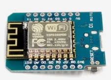
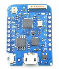
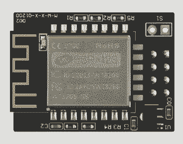
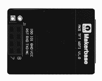
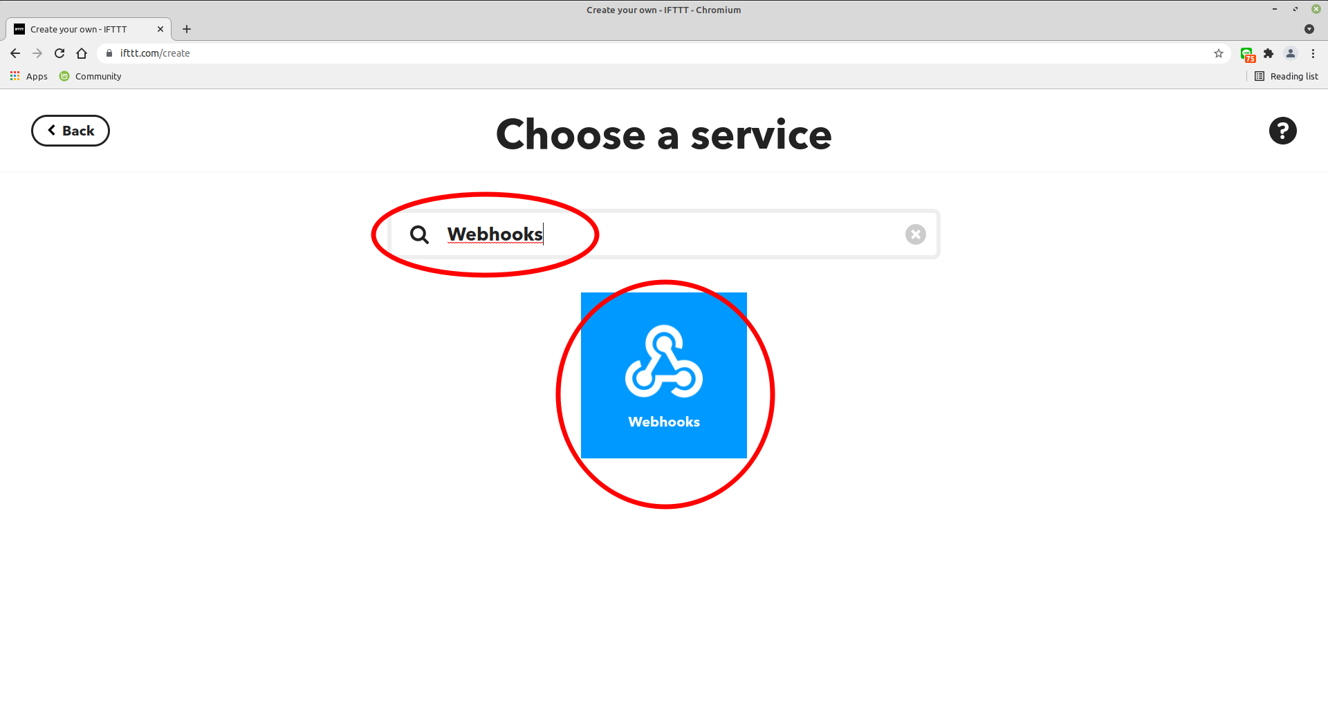
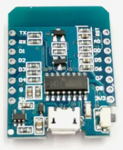
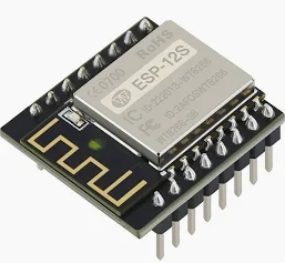
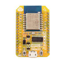
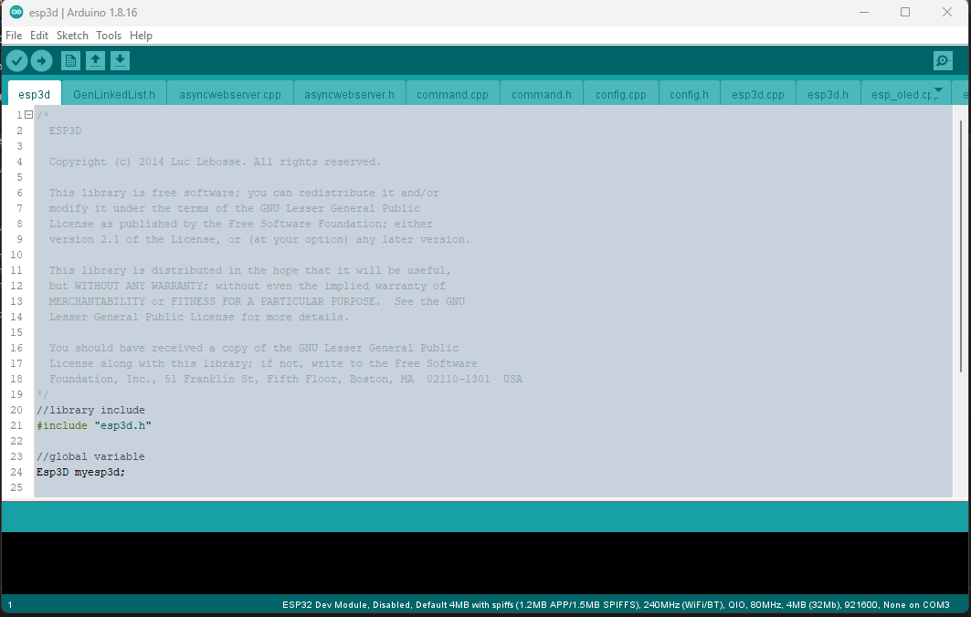
ESP3D is a firmware for ESP8266 and ESP32 boards from espressif, This firmware allows not only to have a cheap bridge between Wifi and serial, but also to have a web UI to configure wifi, to monitor 3D printer/CNC and even control it, and to make things easy, UI is fully customizable without reflashing FW.

Firmware support different target firmwares according version.

Warning

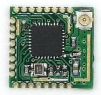
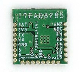
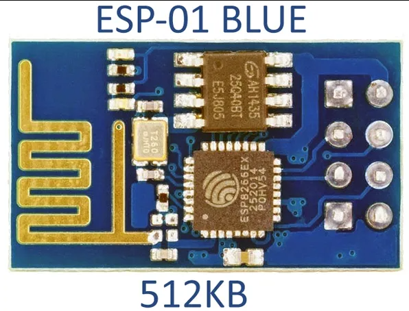
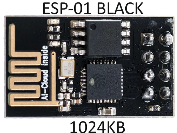
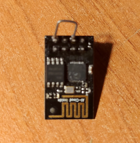
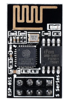
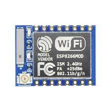
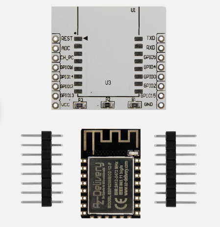
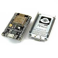
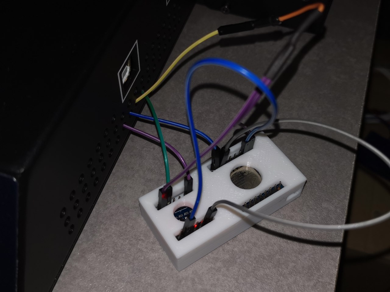
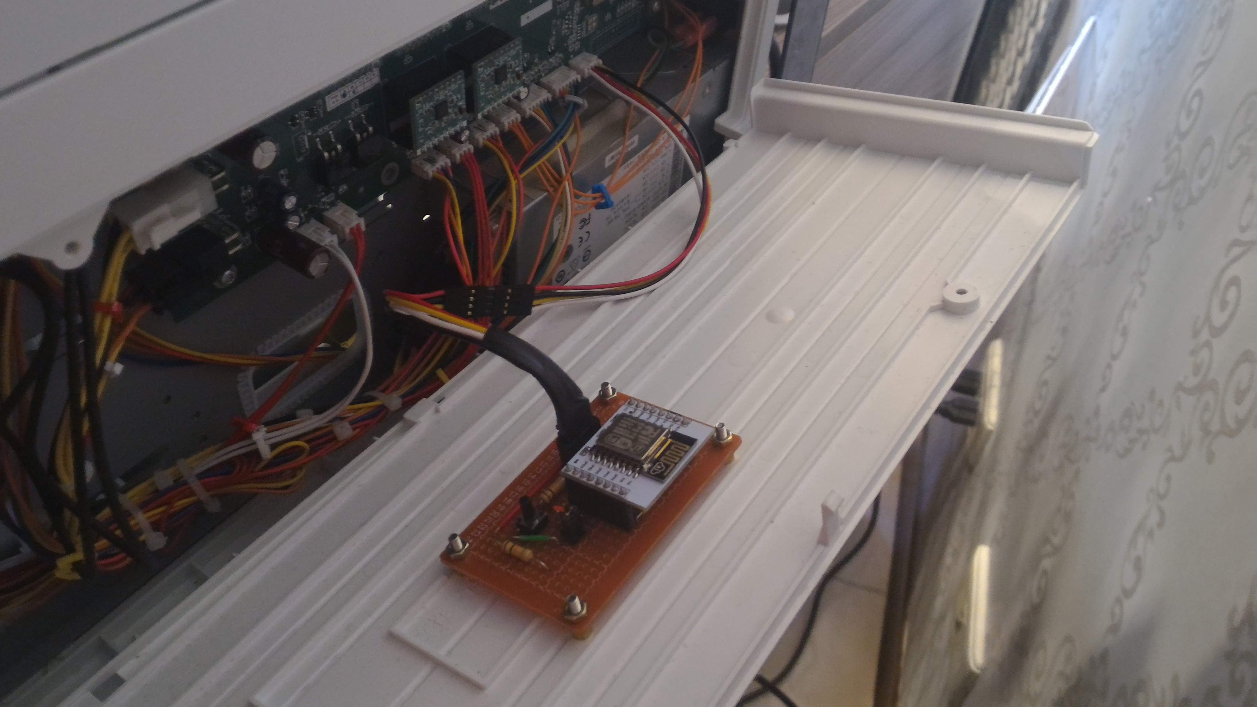
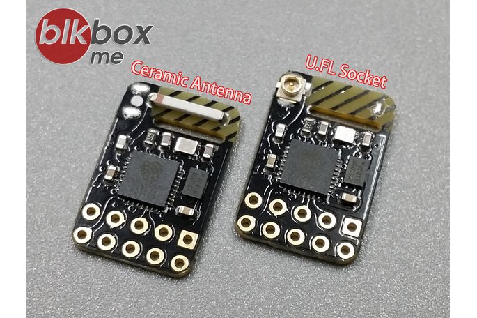
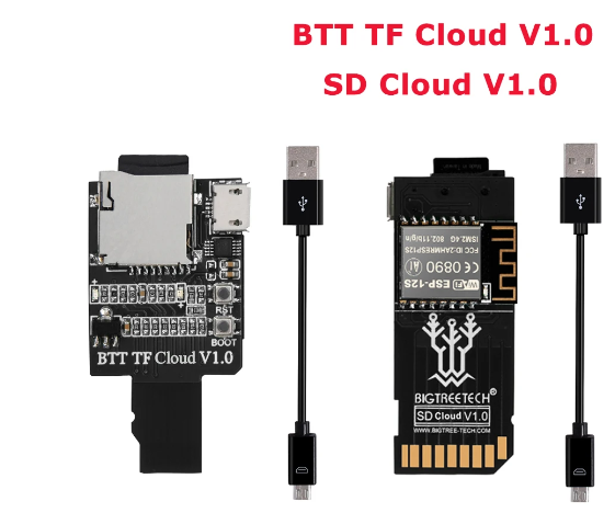
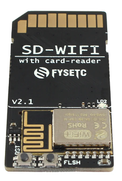
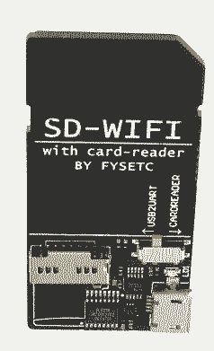
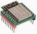
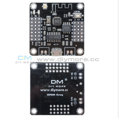
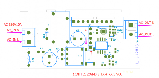
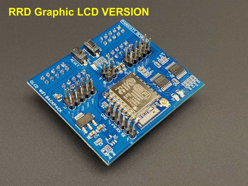
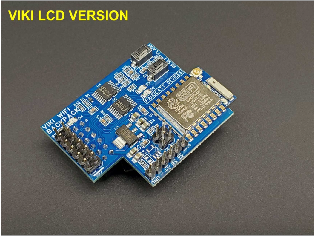
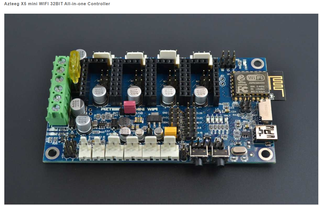
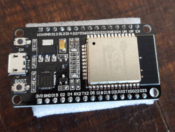
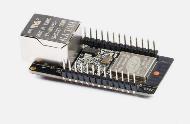
This is for esp8266, esp8285, esp32 boards as daughters boards connected to your main board only. For esp32 board as main board for your 3D Printer please use ESP3DLib

There is one production version and one development version, others versions are no more maintained.

Cybersecurity concerns

If you plan to have access to you ESP from outside of your private network than you need to apply some basic security rules to avoid anybody to be able to access your ESP.

Disclaimer : this is for reference - you are responsible of your board and internet network, we are not responsible for any damage to any of your network appliances.

Recommendations

Following steps must be done before your ESP is visible from public internet:

  • Activate authentication in comfiguration file before flashing
  • Change default user and password (this can be done with commands or webui)

Is also strongly recommended to:

  • Use strong passwords
  • Use unique passwords, not same as for other accounts
  • Change password regularly
  • Configure box to redirect a different port than 80 to the port 80 of ESP
  • Use DMZ feature of your box

Additional tips

  • Remember the web server is not https, this means the server will never be fully secure. In particular, avoid to connect to your printer from any public network you do not own. Stick to your 4G network or other safe places to avoid MITM attack

If any error or need any addition,
please let me know by opening a ticket here
or submit a fix by PR or use the edit button on top menu

Subsections of ESP3D

Version 2.1.X

This version is the production version, features are frozen, only bugfixes are accepted.

Firmware should work with the following firmwares:

The communication between ESP board and target board is done by serial.

The firmware must be used with ESP3D-WEBUI 2.X


If any error or need any addition,
please let me know by opening a ticket here
or submit a fix by PR or use the edit button on top menu

Subsections of Version 2.1.X

Features

The V2.1.X features are :

  • Support for ESP8266, ESP8285 and standard ESP32 board with at least 1Mb of flash
  • Serial/Wifi bridge using configurable port 8888
  • Reset settings using GPIO2 pin
  • Complete configuration by web browser (Station or Access point) or by Serial/telnet commands
  • Authentication (optional) for better security
  • Update firmware by web browser for 4MB boards
  • Captive portal in Access point mode which redirect all unknow call to main page
  • mDNS, this feature is a discovery protocol, it need bonjour installed on computer, supported outof the box by OSX, on Windows and Linux need to be installed
  • SSDP, this feature is a discovery protocol, supported on Windows out of the box
  • Fail safe mode (Access point)is enabled if cannot connect to defined station at boot.
  • Embedded FS uploader and updater
  • Basic OLED screen support
  • Notifications using Line / Pushover / Email
  • DHT sensor support
  • Direct pins control using ESP commands

If any error or need any addition,
please let me know by opening a ticket here
or submit a fix by PR or use the edit button on top menu

Subsections of Hardware

ESP8285 boards


If any error or need any addition,
please let me know by opening a ticket here
or submit a fix by PR or use the edit button on top menu

Subsections of ESP8285 boards

blkboxme

From blkbox

image image

Specs

  • ESP8285 with 1MB flash memory, ceramic antenna
Note

Because flash is only 1MB, OTA/Web Update are not possible


If any error or need any addition,
please let me know by opening a ticket here
or submit a fix by PR or use the edit button on top menu

Itead8285

From Itead, also named PSF-A85

image image image image

Specs

  • ESP8285 with 1MB flash memory, ipex antenna connector
Note

Because flash is only 1MB, OTA/Web Update are not possible


If any error or need any addition,
please let me know by opening a ticket here
or submit a fix by PR or use the edit button on top menu

ESP8266 boards


If any error or need any addition,
please let me know by opening a ticket here
or submit a fix by PR or use the edit button on top menu

Subsections of ESP8266 boards

ESP01 512K

image image

image image

Specs

  • ESP8266 in ESP01 format with 512KB flash memory, ceramic antenna
Note

Because flash is only 512KB, the board is not supported


If any error or need any addition,
please let me know by opening a ticket here
or submit a fix by PR or use the edit button on top menu

ESP01 1M Generic

Specs

  • ESP8266 in ESP01 format (8 pins) with 1MB flash memory, ceramic antenna

image image

Note

Because flash is only 1MB, OTA/Web Update are not possible

Be aware

This ESP01 cannot be used on Bigtreetech boards as it is, a small rework is necessary to bridge VCC pin with CH_PD pin bridge bridge

Pinout

1 2 3 4
GND IO02 IO0 RXD
TXD CH_PD RESET VCC

If any error or need any addition,
please let me know by opening a ticket here
or submit a fix by PR or use the edit button on top menu

ESP01S 1M

Specs

  • ESP8266 in ESP01 format (8 pins, VCC/CH_DP internally bridged ) with 1MB flash memory, ceramic antenna

image image

Note

Because flash is only 1MB, OTA/Web Update are not possible

Pinout

1 2 3 4
GND IO02 IO0 RXD
TXD CH_PD RESET VCC

If any error or need any addition,
please let me know by opening a ticket here
or submit a fix by PR or use the edit button on top menu

ESP07

Specs

  • ESP8266 in ESP7 format with 4MB flash memory, ceramic antenna/ipex connector

image image

Pinout

1 2
RESET TX
ADC RX
CH_PD IO5
IO16 IO4
IO14 IO0
IO12 IO2
IO13 IO15
3.3V GND

If any error or need any addition,
please let me know by opening a ticket here
or submit a fix by PR or use the edit button on top menu

ESP12 e/f

Specs

  • ESP8266 in ESP12 format with 4MB flash memory, ceramic antenna, and voltage regulator

image image

Pinout

1 2
RST TX
ADC RX
CH_PD IO5
IO16 IO4
IO14 IO0
IO12 IO2
IO13 IO15
VCC GND

If any error or need any addition,
please let me know by opening a ticket here
or submit a fix by PR or use the edit button on top menu

Bigtreetech Cloud

image image

Specs

  • ESP8266 with 4MB flash memory, ceramic antenna

github

Note

Because there is no serial connection to printer and the sd connection is based on this project: https://github.com/ardyesp/ESPWebDAV which is a not reliable hack, the boards is not supported

image image

image image


If any error or need any addition,
please let me know by opening a ticket here
or submit a fix by PR or use the edit button on top menu

FYSETC-SD-WIFI

image image

Specs

  • ESP8266 with 4MB flash memory, ceramic antenna

github

Note

Because there is no serial connection to printer and the sd connection is based on this project: https://github.com/ardyesp/ESPWebDAV which is a not reliable hack, the boards is not supported

image image image image

image image


If any error or need any addition,
please let me know by opening a ticket here
or submit a fix by PR or use the edit button on top menu

Bigtreetech WiFi module

Specs

  • ESP8266 in ESP12 format with 4MB flash memory, ceramic antenna, 16 pins

image image

image image

Pinout

1 2
RST TX
ADC RX
EN IO5
IO16 IO4
SCK(IO14) IO0
MISO(IO12) IO2
MOSI(IO13) IO15
3.3V GND

If any error or need any addition,
please let me know by opening a ticket here
or submit a fix by PR or use the edit button on top menu

Diymore

Specs

  • ESP8266 with 4MB flash memory, ceramic antenna/ipex connector

From DM

image image


If any error or need any addition,
please let me know by opening a ticket here
or submit a fix by PR or use the edit button on top menu

Wemos D1 mini

Specs

  • ESP8266 with 4MB flash memory, ceramic antenna

image image

image image

Pinout

1 2
RESET TX
ADC RX
IO16 IO5
IO14 IO4
IO12 IO0
IO13 IO2
IO15 GND
3.3V 5V

If any error or need any addition,
please let me know by opening a ticket here
or submit a fix by PR or use the edit button on top menu

Wemos D1 mini Pro

Specs

  • ESP8266 with 16MB flash memory, ceramic antenna/ipx connector

image image

Pinout

1 2
RESET TX
ADC RX
IO16 IO5
IO14 IO4
IO12 IO0
IO13 IO2
IO15 GND
3.3V 5V

If any error or need any addition,
please let me know by opening a ticket here
or submit a fix by PR or use the edit button on top menu

MKS WiFi Module V1.0 (8 pins)

Specs

  • ESP8266 with 4MB flash memory, ceramic antenna

github

image image image image

Pinout

1 2 3 4
VCC GND IO0 IO4
NC TX RX RST
Note

MKS file upload is not supported, use ESP3D 3.0 or later for MKS protocol support


If any error or need any addition,
please let me know by opening a ticket here
or submit a fix by PR or use the edit button on top menu

MKS WiFi Module V1.1 (16 pins)

Specs

  • ESP8266 with 4MB flash memory, ceramic antenna

github

image image

Pinout

1 2
RESET TX
ADC RX
CH_PD IO5
IO16 IO4
IO14 IO0
IO12 IO2
IO13 IO15
3.3V GND
Note

MKS file upload is not supported, use ESP3D 3.0 or later for MKS protocol support


If any error or need any addition,
please let me know by opening a ticket here
or submit a fix by PR or use the edit button on top menu

Nodemcu V0.8

Specs

  • ESP8266 with 4MB flash memory, ceramic antenna

image image

Pinout

1 2
ADC IO16
RSV IO5
RSV IO4
RSV IO0
RSV IO2
RSV 3.3V
RSV GND
GND IO14
3.3V IO12
GND IO13
3.3V IO15
EN RX
RST TX
GND GND
5V 3.3V

If any error or need any addition,
please let me know by opening a ticket here
or submit a fix by PR or use the edit button on top menu

Nodemcu V1.0

Specs

  • ESP8266 with 4MB flash memory, ceramic antenna

image image

Pinout

1 2
ADC IO16
RSV IO5
RSV IO4
IO10 IO0
IO9 IO2
MOSI 3.3V
CS GND
MISO IO14
CLK IO12
GND IO13
3.3V IO15
EN RX
RST TX
GND GND
5V 3.3V

If any error or need any addition,
please let me know by opening a ticket here
or submit a fix by PR or use the edit button on top menu

SOnOff

Specs

  • ESP8266 with 4MB flash memory, ceramic antenna

image image image image image image


If any error or need any addition,
please let me know by opening a ticket here
or submit a fix by PR or use the edit button on top menu

ESP32 boards


If any error or need any addition,
please let me know by opening a ticket here
or submit a fix by PR or use the edit button on top menu

Subsections of ESP32 boards

Dev Kit V1

Specs

  • ESP32 with 4MB flash memory, ceramic antenna, 30 pins

image image image image


If any error or need any addition,
please let me know by opening a ticket here
or submit a fix by PR or use the edit button on top menu

Dev Kit C V4

Specs

  • ESP32 with 4MB flash memory, ceramic antenna/ipex connector, 38 pins

image image image image


If any error or need any addition,
please let me know by opening a ticket here
or submit a fix by PR or use the edit button on top menu

Heltec Dev board

Specs

  • ESP32 with 4MB flash memory, ceramic antenna, I2C oled screen (SSD1306 128X64, 0x3C, SDA=IO4, SCL=IO15)

image image image image

Note

The screen need to be reset at start using IO16 (Low then High)


If any error or need any addition,
please let me know by opening a ticket here
or submit a fix by PR or use the edit button on top menu

Installation

Setup your development environment

Click on the corresponding image to display how to setup.

Arduino IDE
or

PlatformIO

Tip: The platformIO environment is the easiest to setup, because you do not need to setup the esp core neither the libraries by yourself.

Connect your board

Connection between ESP and printer board needs 4 wires:

  • ESP Tx needs to connect to Rx on MCU of printer board.
  • ESP Rx needs to connect to Tx on MCU of printer board.
  • You also need to power supply ESP board with with GND and 3V3 or 5V.

Connecting ESP board to target board

Be aware that ESP MCU is 3.3V on GPIO pin and some target board can be 3.3V and others 5V, so you may not be able to directly connect ESP board to target board.

Disclaimer : this wiki is for reference - you are responsible of your board supporting or not 5V, we are not responsible for any damage of wrong wiring.

ESP32 and ESP8266 MCU are only supporting 3.3V. Power supply them with 5V will likelly fry them immediatelly. As MCU is supplied at 3.3V, Tx and Rx signals will be at 3.3V even when board is supplied with 5V. Wether Rx pin is supporting 5V is controversial so we will keep on the safe side and only take datahseet as reference. It’s not recommended to have any signal (including Rx) be higher than power supply (3.3V here).

There are several points to take care. One should check that

  1. MCU1 Tx voltage is lower than MCU2 supply voltage
  2. Voh_min of Tx is higher than Vih_min of Rx (to check both ways)
  3. Vol_max of Tx is lower than Vil_max of Rx (to check both ways)

1 is mandatory and resistor voltage divider bridge or level shiffter is recommended
2 & 3 are not destructive there is just a slight risk signals are not read correctly. But it will work in most case as the limit values given by datasheets are rarelly met in mild conditions (using near 25°C and low current flowing from Tx to Rx)

For the divider bridge a value of R1=1k and R2=2.2k will be fine. You could also use 10k and 22k or anything near a factor 2.

step1 step1

Connection diagrams for some printers and ESP boards

Printer motherboards

Anet boards up to v1.5

  • Step 1

You will also have to unsolder the resistors R52 and R53 – they are zero ohm resistors, and serve no other purpose than connecting the atmega chip directly to the onboard USB to UART converter (the CH340 chip). Do it VERY careful – you don’t want to damage your board. If you don’t feel confident – don’t do it.

step1 step1

  • Step 2

Now prepare the printer’s motherboard. It requires a simple modification, that does not interfere with it’s operation afterwards – just solder 3 pin x 2 row male header on J8, and add 2 jumpers (or jumper wires) as shown on the picture:

step1 step1

  • Step 3

Connect the ESP to J3 repsecting pinout

step3 step3

ESP J3
Tx Rx
Rx Tx
GND GND
VCC 3.3V
CH_PD 3.3V

For more Info check lokster | space

For connecting version 1.7 Anet boards

Unlike older boards this board does not require you to remove any resistors.
You will have to solder two wires from number 9 and number 10 its recommender to connect these to pin 1 and 2 of J3 connector.

step1 step1


Anycubic i3 mega - Trigorilla 8bit board

To connect the ESP12e to the UART0. (Credits:197-murdock).
(Green = RX, Blue = TX)
5V (buck to 3.3v if directly connect to ESP - most development ESP boards already have this voltage limited built-in - but check!) and GND can be taken from the AUX3 exposed connector.
UART0 is normally used by USB port so don’t use both together - so this hack piggybacks on that same port at UART level.

step1 step1

step2 step2


AZSMZ LCD board

step1 step1


AZSMZ-mini board

step1 step1

If you don’t have the soldering skills to grab the connectors from the unpopulated ethernet connection, you can also get 3.3v and GND from the ISP header (bottom left on the diagram above).


Azteeg X5 mini board

step1 step1


BIQU KFB2.0 board

all in one Ramps1.4/Mega2560 R3 controller based

step1 step1


Creality CR10 Ender 3 board

For the Sanguino based CR-10 and Ender printers you will need to solder to any of the via circled (can also be done in the backside of board), or to the legs of the Arduino or ftdi. Connect TX from the board to RX of Wemos D1 mini and RX from board to TX of Wemos D1 mini. 5v and GND are located in the six pin header next to the LCD connector.

step1 step1

Since soldering might be difficult because the solder points are so close to each other, another option is to scrape off the insulation from the traces on the backside and solder there. Be extra careful not to scrape the surrounding ground plane. You need suitable fine scraping tools for this. The picture below shows an Ender-2 PCB.

step2 step2


Creality Ender 4 board

You will need to solder to small circle, or to the legs of the ATmega2560 (RXD0 pin 2, TXD0 pin 3)

step1 step1


Davinci 1.0/2.0 board

step1 step1

step2 step2

step3 step3

step4 step4

step5 step5


Davinci 1.0A board

step1 step1

step2 step2

step3 step3

Alternate Module placement for increased WiFi range (outside metal chassis, antenna has vertical polarization)

step4 step4


MKS boards

To connect the ESP3D to the MKS GEN v1.2 (but the v1.3 and above 1.4 is the most used today).

An ESP12E with the standard schematics, the two resistor connected to the RX pin are substituted by a 1N4148 diode, like in the Adafruit Huzzah board.

step1 step1

ESP12E is connected to the AUX1

ESP12E RX is connected to the pin NEAR GND of the upper row (Marked TXD on pinout.)
ESP12E TX is connected to the adiacent pin at the end of the upper row (Marked RXD on pinout.)

step2 step2


MKS Smoothieware board

step1 step1


RADDS board

step1 step1

step2 step2


RAMPS 1.4/Re-ARM board

Ramps 1.4 can be used on Arduino Mega (repetier/marlin) and Re-ARM for ramps boards (smoothieware/marlin)

step1 step1

Alternative pins if use Re-ARM (J4/UART port)

step2 step2


Smoothieboard board

step1 step1


SKR Mini E3 board

This board is from Bigtreetech and went through various hardware revisions; all of them still feature a TFT pin header which is where you can tap the TX and RX needed. The wiring below is made with a 1.2 board, but the same applies for the other revisions as well; if you need the exact schematic for your mainboard version, you can check Bigtreetech’s github repository.

step1 step1

step2 step2

You literally cannot miss it because the TFT connector is labeled on the board; you can use dupont connectors for the wiring job, no soldering skills needed as long as your ESP comes with pre soldered headers. Just a heads up: the TFT connector provides 5V DC, so be sure to provide them on the correct ESP pin and, most importantly, if your ESP can work with 5 volts as input. You should also pay attention on the board orientation in the schematic, although I oriented it the same way as the actual picture on the left so it’s easier for you.


Weedo Tina2 board

This printer is also brand labelled as Monoprice MP cadet 3D printer

step1 step1

In marlin this connection is serial port 3.

Note the Mega2560 is 5V powered and ESP is 3V3 powered.


For printer boards not listed here

Vast majority of printers have an USB port that is converted to UART before going to MCU. Many printers also have additional (unused) UART port you can use. When possible, always use the additional port for connecting ESP to printer board. When no additional UART port is available you might use the Tx and Rx lines between USB/UART converter and MCU but it’s recommended to cut (in a reversible way) the line to USB/UART converter to avoid conflicts.

If the board is ATmega based the simplest way to find a usable UART port for the ESP is to open ATmega datasheet.

ESP boards

ESP-01

  • Use GPIO2 to ground to reset all settings in hard way - 2-6 sec after boot / not before!! Set GPIO2 to ground before boot change boot mode and go to special boot that do not reach FW. Currently boot take 10 sec - giving 8 seconds to connect GPIO2 to GND and do an hard recovery for settings
  • Use GPIO0 to ground to be in update mode

step1 step1


ESP-01 serial wifi module

step1 step1

more info about the Breakout PCB: keyestudio


ESP-12E/F

ESP need 3.3v, it is not 5v tolerant, if printer board use more than 3.3V like 5V on ramps.

step1 step1

you can also use Logic LevelConverter Bi-Directional

step2 step2

In order to flash some ESP12E/F boards via their UART interface, the following pins need to be connected:

  • VCC to GPIO2
  • GND to GPIO0

This has been tested with ESP-12-E boards labeled “ESP8266 For ESP3D FYSETC.COM”


ESP 12F serial wifi module

ESP-12F based serial wifi module (eg from aliexpress ) contains built in 2-way levelshifter/bi-directional logic level converter. So it can be powered via 5V uart from the target’ motherboard.

  • We need to manualy ground the IO0 while powering up to start in flash mode while powering up (there is no switch for that, neither for reset) step1 step1
  • Use FTDI adapter as usb2serial
  • Need to see in console/serial monitor boot mode is (1,7).
    • baudrate: 74880
    • rst cause:2, boot mode:(3,7)
  • Then flash like other esp based board for esp3d

ESP32-Cam

step1 step1

Note: 5V is power supply input and 3V3 is output from regulator. UART Tx and RX signals will be 3.3V


NodeMCU V2/V3

step1 step1


Sonoff

step1 step1

Relay is connected by GPIO12, it can be handled using ESP201 command:

*Get/Set pin value
[ESP201]P<pin> V<value> [PULLUP=YES RAW=YES]
if no V<value> get P<pin> value
if V<value> 0/1 set INPUT_PULLUP value, but for GPIO16 INPUT_PULLDOWN_16
GPIO1 and GPIO3 cannot be used as they are used for serial
if PULLUP=YES set input pull up, if not set input
if RAW=YES do not set pinmode just read value

So [ESP201]P12 V0 should be off and [ESP201]P12 V1 should be on


Wemos D1 mini

Connection with logic level conveter:

step1 step1

example:
step1 step1

printed cases:


If any error or need any addition,
please let me know by opening a ticket here
or submit a fix by PR or use the edit button on top menu

Subsections of Installation

Arduino IDE

Prepare the development environment

  • Please download ide from https://www.arduino.cc/en/software

    Warning

    Please use the Legacy IDE (1.8.X), the Arduino IDE 2.X was not tested and won’t be supported

  • Install the esp core according your target:

    • ESP8266

      Warning

      Please use the version 2.5.2 or 2.7.4 only! Do not use any version upper than 2.7.4

    • ESP32

      Warning

      Please use the version 1.0.4 only! Do not use any version upper than 1.0.4, and only use ESP32 board, other ESP32 flavors(C2, S2, S3, etc) are not supported in this version.

  • Copy the content of the libraries directory to your arduino library directory.

    Warning

    Do not try any version different than the ones provided, they may not work properly.

Open esp3d/esp3d.ino file in Arduino IDE

vscode vscode

ESP3D configuration

Open esp3d/config.h and set features you want.

//Customize ESP3D ////////////////////////////////////////////////////////////////////////
#define ESP8266_MODEL_NAME "ESP8266"
#define ESP8266_MODEL_URL "http://espressif.com/en/products/esp8266/"
#define ESP32_MODEL_NAME "ESP32"
#define ESP32_MODEL_URL "https://www.espressif.com/en/products/hardware/esp-wroom-32/overview"
#define ESP_MODEL_NUMBER "ESP3D 2.1"
#define ESP_MANUFACTURER_NAME "Espressif Systems"
#define ESP_MANUFACTURER_URL "http://espressif.com"
//default name if no mac address is valid
#define ESP_DEFAULT_NAME "MYESP"
//if commented name will follow mac address 3 last digits
//like ESP_XXXXXX (eg:ESP_028E41) to avoid overlap if several ESP3D
#define ESP_HOST_NAME ESP_DEFAULT_NAME

//To allow webupdate using small updater
//#define USE_AS_UPDATER_ONLY

//FEATURES - comment to disable //////////////////////////////////////////////////////////

//WEB_UPDATE_FEATURE: allow to flash fw using web UI
#define WEB_UPDATE_FEATURE

#ifndef USE_AS_UPDATER_ONLY
//Do we use async webserver or not (currntly deprecated do not enable it yet)
//#define ASYNCWEBSERVER

//SERIAL_COMMAND_FEATURE: allow to send command by serial
#define SERIAL_COMMAND_FEATURE

//TCP_IP_DATA_FEATURE: allow to connect serial from TCP/IP
#define TCP_IP_DATA_FEATURE

//NOTIFICATION_FEATURE : allow to push notifications
#define NOTIFICATION_FEATURE

//MKS TFT WIFI support see Wiki for wiring
//#define MKS_TFT_FEATURE

//MDNS_FEATURE: this feature allow  type the name defined
//in web browser by default: http:\\esp8266.local and connect
#define MDNS_FEATURE

//SSDD_FEATURE: this feature is a discovery protocol, supported on Windows out of the box
#define SSDP_FEATURE

//NETBIOS_FEATURE: this feature is a discovery protocol, supported on Windows out of the box
//#define NETBIOS_FEATURE

//CAPTIVE_PORTAL_FEATURE: In SoftAP redirect all unknow call to main page
#define CAPTIVE_PORTAL_FEATURE

//RECOVERY_FEATURE: allow to use GPIO2 pin as hardware reset for EEPROM, add 8s to boot time to let user to jump GPIO2 to GND
//#define RECOVERY_FEATURE

//DIRECT_PIN_FEATURE: allow to access pin using ESP201 command
#define DIRECT_PIN_FEATURE

//ESP_OLED_FEATURE: allow oled screen output
//#define ESP_OLED_FEATURE

//DHT_FEATURE: send update of temperature / humidity based on DHT 11/22
//#define DHT_FEATURE

//AUTHENTICATION_FEATURE: protect pages by login password
//#define AUTHENTICATION_FEATURE

//WS_DATA_FEATURE: allow to connect serial from Websocket
#define WS_DATA_FEATURE

//TIMESTAMP_FEATURE: Time stamp feature on direct SD  files
//#define TIMESTAMP_FEATURE
#endif //USE_AS_UPDATER_ONLY
//Extra features /////////////////////////////////////////////////////////////////////////

//Workaround for Marlin 2.X coldstart
//#define DISABLE_CONNECTING_MSG

//Serial rx buffer size is 256 but can be extended
#define SERIAL_RX_BUFFER_SIZE 512

//Serial Parameters
#define ESP_SERIAL_PARAM SERIAL_8N1

//which serial ESP use to communicate to printer (ESP32 has 3 serials available, ESP8266 only one)
//Uncomment one only
#define USE_SERIAL_0
//For ESP32 Only
//#define USE_SERIAL_1
//#define USE_SERIAL_2

//Pins Definition ////////////////////////////////////////////////////////////////////////
//-1 means use default pins of your board what ever the serial you choose
#define ESP_RX_PIN -1
#define ESP_TX_PIN -1

#ifdef RECOVERY_FEATURE
//pin used to reset setting
#define RESET_CONFIG_PIN 2
#endif

#ifdef DHT_FEATURE
#define ESP_DHT_PIN 2
#endif

//Pins where the screen is connected
#ifdef ESP_OLED_FEATURE
#define OLED_DISPLAY_SSD1306  // OLED Display Type: SSD1306(OLED_DISPLAY_SSD1306) / SH1106(OLED_DISPLAY_SH1106), comment this line out to disable oled
#define OLED_PIN_SDA  4  //5 //SDA;  // i2c SDA Pin
#define OLED_PIN_SCL  15  //4 //SCL;  // i2c SCL Pin
#define OLED_ADDR   0x3c
#define HELTEC_EMBEDDED_PIN 16 //0 to disable
#define OLED_FLIP_VERTICALY 1 //0 to disable
#endif

Configure Flash settings

For ESP8266 with 4MB of flash

  • Board: Generic ESP8266 Module
  • Upload Speed: 115200
  • CPU frequency: 160 MHz
  • Flash Size: 4M (2M SPIFFS)
  • Flash Mode: DIO
  • Flash Frequency: 40Mhz
  • Reset Method: CK
  • Debug Port: Disabled
  • Debug Level: None

For ESP8266 with 1MB of flash (this one may not support Web Update due to limited flash size)

  • Board: Generic ESP8266 Module
  • Upload Speed: 115200
  • CPU frequency: 160 MHz
  • Flash Size: 1M (128K SPIFFS)
  • Flash Mode: DIO
  • Flash Frequency: 40Mhz
  • Reset Method: CK
  • Debug Port: Disabled
  • Debug Level: None

For ESP32 with 4MB of flash

  • Board: ESP32 Dev Module
  • Upload Speed: 115200
  • CPU frequency: 240 MHz
  • Flash Frequency: 80Mhz
  • Flash Mode: QIO
  • Flash Size: 4MB
  • Partition Scheme: Default 4MB with SPIFFS
  • Core Debug Level: None
  • PSRAM: Disabled

Connect your board

Compile and flash your module

Select the port you device is connected to and select Upload from sketch menu to compile and flash.


If any error or need any addition,
please let me know by opening a ticket here
or submit a fix by PR or use the edit button on top menu

VSCode & Platformio

Prepare the development environment

Open the ESP3D directory folder in VSCode

The first time you open the project, vscode need to download all necessary files, so be patient

vscode vscode

ESP3D configuration

Open esp3d/config.h and set features you want.

//Customize ESP3D ////////////////////////////////////////////////////////////////////////
#define ESP8266_MODEL_NAME "ESP8266"
#define ESP8266_MODEL_URL "http://espressif.com/en/products/esp8266/"
#define ESP32_MODEL_NAME "ESP32"
#define ESP32_MODEL_URL "https://www.espressif.com/en/products/hardware/esp-wroom-32/overview"
#define ESP_MODEL_NUMBER "ESP3D 2.1"
#define ESP_MANUFACTURER_NAME "Espressif Systems"
#define ESP_MANUFACTURER_URL "http://espressif.com"
//default name if no mac address is valid
#define ESP_DEFAULT_NAME "MYESP"
//if commented name will follow mac address 3 last digits
//like ESP_XXXXXX (eg:ESP_028E41) to avoid overlap if several ESP3D
#define ESP_HOST_NAME ESP_DEFAULT_NAME

//To allow webupdate using small updater
//#define USE_AS_UPDATER_ONLY

//FEATURES - comment to disable //////////////////////////////////////////////////////////

//WEB_UPDATE_FEATURE: allow to flash fw using web UI
#define WEB_UPDATE_FEATURE

#ifndef USE_AS_UPDATER_ONLY
//Do we use async webserver or not (currntly deprecated do not enable it yet)
//#define ASYNCWEBSERVER

//SERIAL_COMMAND_FEATURE: allow to send command by serial
#define SERIAL_COMMAND_FEATURE

//TCP_IP_DATA_FEATURE: allow to connect serial from TCP/IP
#define TCP_IP_DATA_FEATURE

//NOTIFICATION_FEATURE : allow to push notifications
#define NOTIFICATION_FEATURE

//MKS TFT WIFI support see Wiki for wiring
//#define MKS_TFT_FEATURE

//MDNS_FEATURE: this feature allow  type the name defined
//in web browser by default: http:\\esp8266.local and connect
#define MDNS_FEATURE

//SSDD_FEATURE: this feature is a discovery protocol, supported on Windows out of the box
#define SSDP_FEATURE

//NETBIOS_FEATURE: this feature is a discovery protocol, supported on Windows out of the box
//#define NETBIOS_FEATURE

//CAPTIVE_PORTAL_FEATURE: In SoftAP redirect all unknow call to main page
#define CAPTIVE_PORTAL_FEATURE

//RECOVERY_FEATURE: allow to use GPIO2 pin as hardware reset for EEPROM, add 8s to boot time to let user to jump GPIO2 to GND
//#define RECOVERY_FEATURE

//DIRECT_PIN_FEATURE: allow to access pin using ESP201 command
#define DIRECT_PIN_FEATURE

//ESP_OLED_FEATURE: allow oled screen output
//#define ESP_OLED_FEATURE

//DHT_FEATURE: send update of temperature / humidity based on DHT 11/22
//#define DHT_FEATURE

//AUTHENTICATION_FEATURE: protect pages by login password
//#define AUTHENTICATION_FEATURE

//WS_DATA_FEATURE: allow to connect serial from Websocket
#define WS_DATA_FEATURE

//TIMESTAMP_FEATURE: Time stamp feature on direct SD  files
//#define TIMESTAMP_FEATURE
#endif //USE_AS_UPDATER_ONLY
//Extra features /////////////////////////////////////////////////////////////////////////

//Workaround for Marlin 2.X coldstart
//#define DISABLE_CONNECTING_MSG

//Serial rx buffer size is 256 but can be extended
#define SERIAL_RX_BUFFER_SIZE 512

//Serial Parameters
#define ESP_SERIAL_PARAM SERIAL_8N1

//which serial ESP use to communicate to printer (ESP32 has 3 serials available, ESP8266 only one)
//Uncomment one only
#define USE_SERIAL_0
//For ESP32 Only
//#define USE_SERIAL_1
//#define USE_SERIAL_2

//Pins Definition ////////////////////////////////////////////////////////////////////////
//-1 means use default pins of your board what ever the serial you choose
#define ESP_RX_PIN -1
#define ESP_TX_PIN -1

#ifdef RECOVERY_FEATURE
//pin used to reset setting
#define RESET_CONFIG_PIN 2
#endif

#ifdef DHT_FEATURE
#define ESP_DHT_PIN 2
#endif

//Pins where the screen is connected
#ifdef ESP_OLED_FEATURE
#define OLED_DISPLAY_SSD1306  // OLED Display Type: SSD1306(OLED_DISPLAY_SSD1306) / SH1106(OLED_DISPLAY_SH1106), comment this line out to disable oled
#define OLED_PIN_SDA  4  //5 //SDA;  // i2c SDA Pin
#define OLED_PIN_SCL  15  //4 //SCL;  // i2c SCL Pin
#define OLED_ADDR   0x3c
#define HELTEC_EMBEDDED_PIN 16 //0 to disable
#define OLED_FLIP_VERTICALY 1 //0 to disable
#endif

Select the target in VSCode

vscode vscode

  • [env:esp32dev] for ESP32 boards
  • [env:esp8266] for ESP8266 boards with 4MB flash
  • [env:esp01s_160mhz-2.7.4] for ESP8266 boards with 1MB flash

Connect your board

Compile and flash your module

Use Upload and monitor from the target environment you selected to compile and flash your module.


If any error or need any addition,
please let me know by opening a ticket here
or submit a fix by PR or use the edit button on top menu

Hardware connection

Connection between ESP and printer board needs 4 wires:

  • ESP Tx needs to connect to Rx on MCU of printer board.
  • ESP Rx needs to connect to Tx on MCU of printer board.
  • You also need to power supply ESP board with with GND and 3V3 or 5V.

Connecting ESP board to target board

Be aware that ESP MCU is 3.3V on GPIO pin and some target board can be 3.3V and others 5V, so you may not be able to directly connect ESP board to target board.

Disclaimer : this wiki is for reference - you are responsible of your board supporting or not 5V, we are not responsible for any damage of wrong wiring.

ESP32 and ESP8266 MCU are only supporting 3.3V. Power supply them with 5V will likelly fry them immediatelly. As MCU is supplied at 3.3V, Tx and Rx signals will be at 3.3V even when board is supplied with 5V. Wether Rx pin is supporting 5V is controversial so we will keep on the safe side and only take datahseet as reference. It’s not recommended to have any signal (including Rx) be higher than power supply (3.3V here).

There are several points to take care. One should check that

  1. MCU1 Tx voltage is lower than MCU2 supply voltage
  2. Voh_min of Tx is higher than Vih_min of Rx (to check both ways)
  3. Vol_max of Tx is lower than Vil_max of Rx (to check both ways)

1 is mandatory and resistor voltage divider bridge or level shiffter is recommended
2 & 3 are not destructive there is just a slight risk signals are not read correctly. But it will work in most case as the limit values given by datasheets are rarelly met in mild conditions (using near 25°C and low current flowing from Tx to Rx)

For the divider bridge a value of R1=1k and R2=2.2k will be fine. You could also use 10k and 22k or anything near a factor 2.

step1 step1

Connection diagrams for some printers and ESP boards

Printer motherboards

Anet boards up to v1.5

  • Step 1

You will also have to unsolder the resistors R52 and R53 – they are zero ohm resistors, and serve no other purpose than connecting the atmega chip directly to the onboard USB to UART converter (the CH340 chip). Do it VERY careful – you don’t want to damage your board. If you don’t feel confident – don’t do it.

step1 step1

  • Step 2

Now prepare the printer’s motherboard. It requires a simple modification, that does not interfere with it’s operation afterwards – just solder 3 pin x 2 row male header on J8, and add 2 jumpers (or jumper wires) as shown on the picture:

step1 step1

  • Step 3

Connect the ESP to J3 repsecting pinout

step3 step3

ESP J3
Tx Rx
Rx Tx
GND GND
VCC 3.3V
CH_PD 3.3V

For more Info check lokster | space

For connecting version 1.7 Anet boards

Unlike older boards this board does not require you to remove any resistors.
You will have to solder two wires from number 9 and number 10 its recommender to connect these to pin 1 and 2 of J3 connector.

step1 step1


Anycubic i3 mega - Trigorilla 8bit board

To connect the ESP12e to the UART0. (Credits:197-murdock).
(Green = RX, Blue = TX)
5V (buck to 3.3v if directly connect to ESP - most development ESP boards already have this voltage limited built-in - but check!) and GND can be taken from the AUX3 exposed connector.
UART0 is normally used by USB port so don’t use both together - so this hack piggybacks on that same port at UART level.

step1 step1

step2 step2


AZSMZ LCD board

step1 step1


AZSMZ-mini board

step1 step1

If you don’t have the soldering skills to grab the connectors from the unpopulated ethernet connection, you can also get 3.3v and GND from the ISP header (bottom left on the diagram above).


Azteeg X5 mini board

step1 step1


BIQU KFB2.0 board

all in one Ramps1.4/Mega2560 R3 controller based

step1 step1


Creality CR10 Ender 3 board

For the Sanguino based CR-10 and Ender printers you will need to solder to any of the via circled (can also be done in the backside of board), or to the legs of the Arduino or ftdi. Connect TX from the board to RX of Wemos D1 mini and RX from board to TX of Wemos D1 mini. 5v and GND are located in the six pin header next to the LCD connector.

step1 step1

Since soldering might be difficult because the solder points are so close to each other, another option is to scrape off the insulation from the traces on the backside and solder there. Be extra careful not to scrape the surrounding ground plane. You need suitable fine scraping tools for this. The picture below shows an Ender-2 PCB.

step2 step2


Creality Ender 4 board

You will need to solder to small circle, or to the legs of the ATmega2560 (RXD0 pin 2, TXD0 pin 3)

step1 step1


Davinci 1.0/2.0 board

step1 step1

step2 step2

step3 step3

step4 step4

step5 step5


Davinci 1.0A board

step1 step1

step2 step2

step3 step3

Alternate Module placement for increased WiFi range (outside metal chassis, antenna has vertical polarization)

step4 step4


MKS boards

To connect the ESP3D to the MKS GEN v1.2 (but the v1.3 and above 1.4 is the most used today).

An ESP12E with the standard schematics, the two resistor connected to the RX pin are substituted by a 1N4148 diode, like in the Adafruit Huzzah board.

step1 step1

ESP12E is connected to the AUX1

ESP12E RX is connected to the pin NEAR GND of the upper row (Marked TXD on pinout.)
ESP12E TX is connected to the adiacent pin at the end of the upper row (Marked RXD on pinout.)

step2 step2


MKS Smoothieware board

step1 step1


RADDS board

step1 step1

step2 step2


RAMPS 1.4/Re-ARM board

Ramps 1.4 can be used on Arduino Mega (repetier/marlin) and Re-ARM for ramps boards (smoothieware/marlin)

step1 step1

Alternative pins if use Re-ARM (J4/UART port)

step2 step2


Smoothieboard board

step1 step1


SKR Mini E3 board

This board is from Bigtreetech and went through various hardware revisions; all of them still feature a TFT pin header which is where you can tap the TX and RX needed. The wiring below is made with a 1.2 board, but the same applies for the other revisions as well; if you need the exact schematic for your mainboard version, you can check Bigtreetech’s github repository.

step1 step1

step2 step2

You literally cannot miss it because the TFT connector is labeled on the board; you can use dupont connectors for the wiring job, no soldering skills needed as long as your ESP comes with pre soldered headers. Just a heads up: the TFT connector provides 5V DC, so be sure to provide them on the correct ESP pin and, most importantly, if your ESP can work with 5 volts as input. You should also pay attention on the board orientation in the schematic, although I oriented it the same way as the actual picture on the left so it’s easier for you.


Weedo Tina2 board

This printer is also brand labelled as Monoprice MP cadet 3D printer

step1 step1

In marlin this connection is serial port 3.

Note the Mega2560 is 5V powered and ESP is 3V3 powered.


For printer boards not listed here

Vast majority of printers have an USB port that is converted to UART before going to MCU. Many printers also have additional (unused) UART port you can use. When possible, always use the additional port for connecting ESP to printer board. When no additional UART port is available you might use the Tx and Rx lines between USB/UART converter and MCU but it’s recommended to cut (in a reversible way) the line to USB/UART converter to avoid conflicts.

If the board is ATmega based the simplest way to find a usable UART port for the ESP is to open ATmega datasheet.

ESP boards

ESP-01

  • Use GPIO2 to ground to reset all settings in hard way - 2-6 sec after boot / not before!! Set GPIO2 to ground before boot change boot mode and go to special boot that do not reach FW. Currently boot take 10 sec - giving 8 seconds to connect GPIO2 to GND and do an hard recovery for settings
  • Use GPIO0 to ground to be in update mode

step1 step1


ESP-01 serial wifi module

step1 step1

more info about the Breakout PCB: keyestudio


ESP-12E/F

ESP need 3.3v, it is not 5v tolerant, if printer board use more than 3.3V like 5V on ramps.

step1 step1

you can also use Logic LevelConverter Bi-Directional

step2 step2

In order to flash some ESP12E/F boards via their UART interface, the following pins need to be connected:

  • VCC to GPIO2
  • GND to GPIO0

This has been tested with ESP-12-E boards labeled “ESP8266 For ESP3D FYSETC.COM”


ESP 12F serial wifi module

ESP-12F based serial wifi module (eg from aliexpress ) contains built in 2-way levelshifter/bi-directional logic level converter. So it can be powered via 5V uart from the target’ motherboard.

  • We need to manualy ground the IO0 while powering up to start in flash mode while powering up (there is no switch for that, neither for reset) step1 step1
  • Use FTDI adapter as usb2serial
  • Need to see in console/serial monitor boot mode is (1,7).
    • baudrate: 74880
    • rst cause:2, boot mode:(3,7)
  • Then flash like other esp based board for esp3d

ESP32-Cam

step1 step1

Note: 5V is power supply input and 3V3 is output from regulator. UART Tx and RX signals will be 3.3V


NodeMCU V2/V3

step1 step1


Sonoff

step1 step1

Relay is connected by GPIO12, it can be handled using ESP201 command:

*Get/Set pin value
[ESP201]P<pin> V<value> [PULLUP=YES RAW=YES]
if no V<value> get P<pin> value
if V<value> 0/1 set INPUT_PULLUP value, but for GPIO16 INPUT_PULLDOWN_16
GPIO1 and GPIO3 cannot be used as they are used for serial
if PULLUP=YES set input pull up, if not set input
if RAW=YES do not set pinmode just read value

So [ESP201]P12 V0 should be off and [ESP201]P12 V1 should be on


Wemos D1 mini

Connection with logic level conveter:

step1 step1

example:
step1 step1

printed cases:


If any error or need any addition,
please let me know by opening a ticket here
or submit a fix by PR or use the edit button on top menu

Documentation

The documentation section will help you on:


If any error or need any addition,
please let me know by opening a ticket here
or submit a fix by PR or use the edit button on top menu

Subsections of Documentation

ESP3D commands

Conventions

Please note all commands are in format [ESPxx]. These first brackets [] are not optional.
Most of the time givin no argument will return current configuration If authentication is on, somme commands will need admin password. They are recognised by the optional argument pwd=<admin password> in command line.

Commands

  • Get/change STA SSID
    [ESP100] <SSID> pwd=<admin password>

  • Change STA Password
    [ESP101] <Password> pwd=<admin password>

  • Get/change Hostname
    [ESP102] <hostname> pwd=<admin password>

  • Get/change Wifi mode (STA/AP)
    [ESP103] <mode> pwd=<admin password>

  • Get/change STA IP mode (DHCP/STATIC)
    [ESP104] <mode> pwd=<admin password>

  • Get/change AP SSID
    [ESP105] <SSID> pwd=<admin password>

  • Change AP Password
    [ESP106] <Password> pwd=<admin password>

  • Get/change AP IP mode (DHCP/STATIC)
    [ESP107] <mode> pwd=<admin password>

  • Get/change wifi state (on/off)
    [ESP110] <state> pwd=<admin password>

  • Get current IP
    [ESP111]

  • Get/Change hostname
    [ESP112] <hostname>

  • Get/Set pin value
    [ESP201] P<pin> V<value> PULLUP=<YES/NO> RAW=<YES/NO> ANALOG=<NO/YES> ANALOG_RANGE=[255/1024] CLEARCHANNELS=<NO/YES} pwd=<admin password>
    if no V get P value
    if V 0/1 set INPUT_PULLUP value, but for GPIO16 INPUT_PULLDOWN_16 GPIO1 and GPIO3 cannot be used as they are used for serial
    if PULLUP=YES set input pull up, if not set input
    if RAW=YES do not set pinmode just read value

  • Output to oled column C and line L
    [ESP210] C=<col> L=<line> T=<Text>

  • Output to oled line 1
    [ESP211] <Text>

  • Output to oled line 2
    [ESP212] <Text>

  • Output to oled line 3
    [ESP213] <Text>

  • Output to oled line 4
    [ESP214] <Text>

  • Delay
    [ESP290] <delayMs> pwd=<admin password>

  • Get EEPROM mapping version
    [ESP300]

  • Get full EEPROM settings content
    but do not give any passwords can filter if only need wifi or printer [ESP400] <network/printer>

  • Set EEPROM setting
    [ESP401] P=<position> T={B | I | S | A} V=<value> pwd=<user/admin password>
    T type: B(byte), I(integer/long), S(string), A(IP address / mask)
    P position: address in EEPROM

     Description:        Positions: 
    EP_WIFI_MODE             0    //1 byte = flag
    EP_STA_SSID              1    //33 bytes 32+1 = string  ; warning does not support multibyte char like chinese
    EP_STA_PASSWORD          34   //65 bytes 64 +1 = string ;warning  does not support multibyte char like chinese
    EP_STA_IP_MODE           99   //1 byte = flag
    EP_STA_IP_VALUE          100  //4  bytes xxx.xxx.xxx.xxx
    EP_STA_MASK_VALUE        104  //4  bytes xxx.xxx.xxx.xxx
    EP_STA_GATEWAY_VALUE     108  //4  bytes xxx.xxx.xxx.xxx
    EP_BAUD_RATE             112  //4  bytes = int
    EP_STA_PHY_MODE          116  //1 byte = flag
    EP_SLEEP_MODE            117  //1 byte = flag
    EP_CHANNEL               118  //1 byte = flag
    EP_AUTH_TYPE             119  //1 byte = flag
    EP_SSID_VISIBLE          120  //1 byte = flag
    EP_WEB_PORT              121  //4  bytes = int
    EP_DATA_PORT             125  //4  bytes = int
    EP_OUTPUT_FLAG           129  //1  bytes = flag
    EP_HOSTNAME              130  //33 bytes 32+1 = string  ; warning does  not support multibyte char like chinese
    EP_DHT_INTERVAL          164  //4  bytes = int
    EP_FREE_INT2             168  //4  bytes = int
    EP_FREE_INT3             172  //4  bytes = int
    EP_ADMIN_PWD             176  //21  bytes 20+1 = string  ; warning does  not support multibyte char like chinese
    EP_USER_PWD              197  //21  bytes 20+1 = string  ; warning does  not support multibyte char like chinese
    EP_AP_SSID               218  //33 bytes 32+1 = string  ; warning  does not support multibyte char like chinese
    EP_AP_PASSWORD           251  //65 bytes 64 +1 = string ;warning  does not support multibyte char like chinese
    EP_AP_IP_VALUE           316  //4  bytes xxx.xxx.xxx.xxx
    EP_AP_MASK_VALUE         320  //4  bytes xxx.xxx.xxx.xxx
    EP_AP_GATEWAY_VALUE      324  //4  bytes xxx.xxx.xxx.xxx
    EP_AP_IP_MODE            329  //1 byte = flag
    EP_AP_PHY_MODE           330  //1 byte = flag
    EP_FREE_STRING1          331  //129 bytes 128+1 = string  ; warning  does not support multibyte char like chinese
    EP_DHT_TYPE              460  //1  bytes = flag
    EP_TARGET_FW             461  //1  bytes = flag
  • Get available AP list (limited to 30)
    [ESP410]<plain>
    Output is JSON or plain text according parameter

  • Get current settings of ESP3D
    [ESP420]<plain>
    Output is JSON or plain text according parameter

  • Get/Set ESP mode (RESET, SAFEMODE, CONFIG, RESTART)
    [ESP444] <mode> pwd=<admin password>
    if authentication is on, need admin password for RESET, RESTART and SAFEMODE

  • Send GCode with check sum caching right line numbering
    [ESP500] <gcode>

  • Send line checksum
    [ESP501] <line>

  • Change / Reset password
    [ESP550] <password> pwd=<admin password>
    If no password set it use default one

  • Change / Reset user password
    [ESP555] <password> pwd=<admin/user password>
    If no password set it use default one

  • Send notification
    [ESP600] <message> pwd=<admin password>

  • Set/Get notification settings (type can be NONE, PUSHOVER, EMAIL, LINE)
    [ESP610] type=<type> T1=<token1> T2=<token2> TS=<Settings> pwd=<admin password> Get will give type and settings only not the protected T1/T2

  • Read SPIFFS file and send each line to serial
    [ESP700] <filename>

  • Format SPIFFS
    [ESP710] FORMAT pwd=<admin password>

  • Get SPIFFS total size and used size
    [ESP720]

  • Get fw version and basic information
    [ESP800]

  • Get fw target
    [ESP801]

  • Get state / Set Enable / Disable Serial Communication (state: {ENABLE, DISABLE)
    [ESP900] <state>


If any error or need any addition,
please let me know by opening a ticket here
or submit a fix by PR or use the edit button on top menu

Notifications

You can use only one type of notification from the following ones:

  • Pushover, which is a pay service

    Please follow this link for more information on how to setup a pushover notification service

  • Line, which is a free service

    Please follow this link for more information on how to setup a line notification service

  • Email using SMTP and HTTPS

    Please follow this link for more information on how to setup a email notification service

  • IFTTT webhook, which is a free service up to 5 applets

    Please follow this link for more information on how to setup a pushover iftt service

How to send message ?

Just add following command in your slicer’s end script, or manualy on your GCODE file:
[ESP600]msg pwd=<admin password>

How to ask printer to send command from file played from SD ?

  • on Repetier
    M118 [ESP600]msg

  • on Marlin
    M118 P0 [ESP600]msg

  • on Smoothieware
    echo [ESP600]msg


If any error or need any addition,
please let me know by opening a ticket here
or submit a fix by PR or use the edit button on top menu

Subsections of Notifications

Pushover Notification

Pushover is paid service

Considering you have pushover account (even just trial) and you already installed pushover client on you phone/PC:

1 - Go to https://pushover.net/ and connect with email and password
image image

2 - Once connected you will be able to get the token 1, the user token
image image

3 - You also need to generate an application token, which is the token 2
image image

4 - The token 2 generation: image image

5 - Save the generate token 1 and token 2 in ESP3D, and set PUSHOVER as notification supplier
[ESP610]type=PUSHOVER T1=xxxxxxxxxxxxxxxxxx T2=yyyyyyyyyyyyyyyyy

6 - type [ESP610] to verify (T1 and T2 won’t be displayed)

7 - Try to send message:
[ESP600]Hi there, test from ESP3D


If any error or need any addition,
please let me know by opening a ticket here
or submit a fix by PR or use the edit button on top menu

Line Notification

Line is free service

Considering you have line account and you already installed line on you phone/PC:

1 - Go to https://notify-bot.line.me/my/ and connect with email and password image image

2 - Once connected you will be able to generate token
image image

3 - Type token name on top, select recipient(s) and press Generate token
image image

4 - Once token is created you need to copy it
image image

5 - You can create as many tokens you want, and delete the ones you do not need
image image

6 - Save the generate token in ESP3D, and set LINE as notification supplier
[ESP610]type=LINE T1=xxxxxxxxxxxxxxxxxx

7 - type [ESP610] to verify (T1 won’t be displayed)

8 - Try to send message:
[ESP600]Hi there, test from ESP3D


If any error or need any addition,
please let me know by opening a ticket here
or submit a fix by PR or use the edit button on top menu

Email Notification

Email Notification is using SMTP and HTTPS, so you need to collect the following information fof your email supplier

  • smtp server address and https port
  • smtp username/ID
  • smtp password

ESP3D use the parameters as follow:

  • token 1 = ID to login to your email supplier
  • token 2 = Password to login to your email supplier
  • token settings = the_recipient email#smtp_server:port where # and : are fields separators.

For example: luc@gmail.com#smtp.gmail.com:465

1 -Save the token 1, token 2 and token settings in ESP3D, and set EMAIL as notification supplier
[ESP610]type=EMAIL T1=luc@gmail.com T2=mypassword TS=luc@gmail.com#smtp.gmail.com:465

2 - Type [ESP610] to verify (T1 and T2 won’t be displayed)

3 - Try to send message:
[ESP600]Hi there, test from ESP3D

4 - Important : if you are using Gmail there is an additional step, as by default https access is disabled.
go to : https://myaccount.google.com/lesssecureapps and allow less secure applications to connect gmail enabling http access gmail enabling http access


If any error or need any addition,
please let me know by opening a ticket here
or submit a fix by PR or use the edit button on top menu

IFTTT Notification

IFTTT is free service up to 5 applets

IFTTT is a wrapper that allows several kind of notifications, please refer to it documentation.
ESP3D use the webhook method.

1 - If you do not have IFTTT account you can create for free to use up to 5 applets. IFFTT account creation step IFFTT account creation step

2 - Create New applet
Create applet Create applet

  • Create new trigger
    create trigger create trigger

  • The trigger is a webhook
    trigger is a webhook trigger is a webhook

  • Choose Web request
    choose web request choose web request

  • Set the event name set event name set event name

  • Define the action you want define wanted action define wanted action

  • Select the service you want to use
    As you can see there are a lot, let use email as example, but you can select any one that fit your needs select device select device select device select device

  • Define the message
    IFTTT allows some variables:

    • title from ESP3D –> value1
    • message from ESP3D –> value2
    • ESP3D hostname –> value3

    define message define message

  • Applet is created applet created applet created

3 - Retrieve the webhook key

  • Go to settings settings settings

  • Select service service service

  • Select webhook webhook webhook

  • Choose documentation documentation documentation

  • Copy the key copy key copy key

4 - Save the generate token and chatID in ESP3D, and set IFTTT as notification supplier
[ESP610]type=IFTTT T1={event} T2={webhooks_key}

5 - type [ESP610] to verify (T1/T2 won’t be displayed)

6 - Try to send message:
[ESP600]Hi there, test from ESP3D

7 - Verify the workflow

  • Go to Applets
    applets applets
  • Select Activity
    activity activity
  • Select the flow to display
    flow to display flow to display

Note: This documentation is not exaustive due to huge features of IFTTT notifications service but base is always same :

IFThis => webhooks based on webrequest
THENThat => IFTTT notification service

If any error or need any addition,
please let me know by opening a ticket here
or submit a fix by PR or use the edit button on top menu

API

Web Handlers

/ (GET)

root is the default handler where all files will be served, if no file is defined, it looks for index.html or index.html.gz (compressed) if you call specific file, it will look for the filename and filename.gz (compressed) if no file is defined and there is not index.html(.gz) it will display embedded page another way to show the embedded page is /?forcefallback=yes

/files (GET/POST)

this handler handle all commands for FS, including upload on FS.
possible options/arguments are:

  • quiet=yes can be used when you don’t want list files but just upload them
  • path=... define the path to the file
  • action=... define the action to execute which can be:
    - delete
    delete the file defined by filename=... it will also use path=... to do full path
    - deletedir
    delete the directory defined by filename=... it will also use path=... to do full path
    - createdir create the directory defined by filename=... it will also use path=... to do full path
  • <filename>S=... give the size of uploaded file with name, need to be set before file is set in upload, POST only

the output is a json file:

```
{   
    "files":[ //the files list  
        {  
            "name":"index.html.gz", //the name of the file
            "size":"83.46 KB", //the formated size of the file 
            "time":"2022-09-04 11:56:05" //the time when the file was modified last time, this one is optional and depend on (FILESYSTEM_TIMESTAMP_FEATURE)
        },
        {
            "name":"subdir", //the name of the file / directory
            "size":"-1", //the size is -1 because it is a directory
            "time":"" //no time for directories optional as depend on (FILESYSTEM_TIMESTAMP_FEATURE)
        }
    ],
    "path":"/", //current path
    "occupation":"52", //% of occupation
    "status":"subdir created", //status 
    "total":"192.00 KB", //Formated total space of Filesystem
    "used":"100.00 KB" //Formated used space of Filesystem
}
```

/upload_serial (POST)

this handler is for uploading files to printer SD using M28/M29 protocol

/command (GET)

this handler is for all commands the parameter is cmd=... if it is an [ESPXXX] command the answer is the [ESPXXX] response if it is not an [ESPXXX] command the answer is ESP3D says: command forwarded and can be ignored

/login (GET/POST)

this handler is for authentication function if enabled possible options/arguments are:
- DISCONNECT=YES it will clear current session, remove authentication cookie, set status to disconnected and response code to 401 - SUBMIT=YES to login it will need also PASSWORD=... and USER=..., the answer will be 200 if success and 401 if failed if user is already authenticated it can use NEWPASSWORD=... instead of PASSWORD=... to change his password, if successful answer will be returned with code 200, otherwise code will be 500 if change failed or if password format is invalid

/config (GET)

this handler is a shortcut to [ESP420] command in text mode, to get output in json add json=yes

/updatefw (POST)

this handler is for FW upload and update

/description.xml (GET)

this handler is for SSDP if enabled to present device informations

<root xmlns="urn:schemas-upnp-org:device-1-0">
    <specVersion>
        <major>1</major>
        <minor>0</minor>
    </specVersion>
    <URLBase>http://192.168.2.178:80/</URLBase>
    <device>
        <deviceType>urn:schemas-upnp-org:device:upnp:rootdevice:1</deviceType>
        <friendlyName>esp3d</friendlyName>
        <presentationURL>/</presentationURL>
        <serialNumber>52332</serialNumber>
        <modelName>ESP Board</modelName>
        <modelDescription/>
        <modelNumber>ESP3D 3.0</modelNumber>
        <modelURL>https://www.espressif.com/en/products/devkits</modelURL>
        <manufacturer>Espressif Systems</manufacturer>
        <manufacturerURL>https://www.espressif.com</manufacturerURL>
        <UDN>uuid:38323636-4558-4dda-9188-cda0e600cc6c</UDN>
        <serviceList/>
        <iconList/>
    </device>
</root>

Captive portal bypass handlers

to avoid a redirect to index.html and so a refresh of the page, some classic handler have been added so they all go to / handler actually

  • /generate_204
  • /gconnectivitycheck.gstatic.com
  • /fwlink/

Web Socket

Only for WebUI not for bridge data

use subprotocol arduino and web port +1 (e.g: 80+1=>81)

text mode

Reserved messages between webui / ESP Format: <label>:<message>

  • from ESP to WebUI

    • CURRENT_ID:<id> Sent when client is connecting, it is the last ID used and become the active ID

    • ACTIVE_ID:<id> Broadcast current active ID, when new client is connecting, client without this is should close, ESP WS Server close all open WS connections but this one also

    • ERROR:<code>:<message> If an error raise when doing upload, it informs client it must stop uploading because sometimes the http answer is not possible, or cannot cancel the upload, this is a workaround as there is no API in current webserver to cancel active upload

    • DHT: <value>C The DHT sensor connected to ESP like DHT22

binary mode

Reserved

  • from ESP to WebUI serial stream data from ESP to WebUI

  • from WEBUI to ESP
    [Not used]


If any error or need any addition,
please let me know by opening a ticket here
or submit a fix by PR or use the edit button on top menu

About SD card

Warning

The SD transfer use the GCODE protocol based on M28/M29 commands, this protocol is often broken by external queries or even auto reporting. Additionnaly the SD transfer is very slow: ~0.4KB/s, which make it almost unusable.

So this protocol is no more supported in ESP3D, and feature is provided as it is.

The only existing reliable solution to be used in addition of ESP3D 2.1X, is to use a WiFi SD card like Toshiba FlashAir, which is no more produced.

ESP3D 3.0 has some existing solution and some ongoing plan for better SD support depending on hardware used.


If any error or need any addition,
please let me know by opening a ticket here
or submit a fix by PR or use the edit button on top menu

Showcase

On a Davinci 2.0

board board board board board board


If any error or need any addition,
please let me know by opening a ticket here
or submit a fix by PR or use the edit button on top menu

Credits

Big thanks to :

  • @disneysw for bringing this module idea
  • @lkarlslund for suggestion about independent reset using GPIO2
  • Roy Cortes from Panucatt Devices for supporting and pushing me implementing great features
  • all contributors, feedbacks owners and donations.

Embedded code / inspiration code

Libraries


If any error or need any addition,
please let me know by opening a ticket here
or submit a fix by PR or use the edit button on top menu

Version 3.X

This version is the development version, features can change anytime, feedback, PR and suggestions are welcome.

Firmware should work with the following firmwares:

The communication between ESP board and target board is done by serial.

The firmware must be used with ESP3D-WEBUI 3.X

To help and simplify the configuration, a configurator is available:


If any error or need any addition,
please let me know by opening a ticket here
or submit a fix by PR or use the edit button on top menu

Subsections of Version 3.X

Features

The V3.X features are :

  • Embedded maintenance page (terminal / local FS update / ESP3D Firmware update)
  • WebUI support
  • ESP8285 / ESP8266 / ESP32 / ESP32-S2 / ESP32-S3 / ESP32-C3 support
  • Wifi / ethernet support
  • Raw TCP / serial bridge support (light telnet)
  • Boot delay configuration
  • Websocket / serial bridge support
  • Serial / Serial bridge support
  • Bluetooth Serial bridge support (when BT supported)
  • MKS Serial protocol support
  • Serial commands configurations
  • Authentication support (admin / user)
  • FTP support (limited to 1 connection at once)
  • WebDav support
  • Local FS support:
    • Little FS
    • Fat (ESP32 only)
  • SD support
    • File format
      • Native SPI
      • Native SDIO (ESP32 only)
      • SDFat 2.x
    • Connection
      • Direct connection
        • e.g.: ESP32cam
      • Sharing connection using hardware switch
        • e.g.: Panucatt Wifi Backpack / Azteeg X5 WiFi
      • MKS fast upload by serial
    • NOT SUPPORTED ANYMORE
      • M28/M29 File transfer protocol
    • Serial file transfer using custom protocol (planned)
  • USB support
    • planned
  • Global FS under FTP / Webdav : SD + Local FS in same directory
  • Buzzer support
  • Recovery pin support
  • Pins control by commands
  • ESP32 Camera support (only with PSRAM)
  • Basic oled screen support
    • I2C SSD1306 128x64
    • I2C SSDSH1106 132x64
  • Basic tft screen support
    • SPI ST7789 135x240
    • SPI ST7789 240x240
  • Time synchronization support (manual / internet server)
  • Lua interpreter support (Work in progress)
  • Notifications support
    • WebUI
    • TFT/OLED
    • Email
    • Line
    • Telegram
    • PushOver
    • IFTTT
    • Home Assistant
  • Sensors support
    • DHT 11/22
    • Analog
    • BMX280
  • Auto script support at start
  • Basic Host GCODE stream for macros hosted on local FS (Work in Progress)
  • Update
    • ESP3D configuration using ini file on SD
    • ESP3D update using binary file on SD
    • OTA support
    • Update by WebUI

If any error or need any addition,
please let me know by opening a ticket here
or submit a fix by PR or use the edit button on top menu

Hardware


If any error or need any addition,
please let me know by opening a ticket here
or submit a fix by PR or use the edit button on top menu

Subsections of Hardware

ESP boards


If any error or need any addition,
please let me know by opening a ticket here
or submit a fix by PR or use the edit button on top menu

Subsections of ESP boards

ESP8285 boards


If any error or need any addition,
please let me know by opening a ticket here
or submit a fix by PR or use the edit button on top menu

Subsections of ESP8285 boards

blkboxme

From blkbox

image image

Specs

  • ESP8285 with 1MB flash memory, ceramic antenna
Note

Because flash is only 1MB, OTA/Web Update are not possible


If any error or need any addition,
please let me know by opening a ticket here
or submit a fix by PR or use the edit button on top menu

Itead8285

From Itead, also named PSF-A85

image image image image

Specs

  • ESP8285 with 1MB flash memory, ipex antenna connector
Note

Because flash is only 1MB, OTA/Web Update are not possible


If any error or need any addition,
please let me know by opening a ticket here
or submit a fix by PR or use the edit button on top menu

ESP8266 boards


If any error or need any addition,
please let me know by opening a ticket here
or submit a fix by PR or use the edit button on top menu

Subsections of ESP8266 boards

ESP01 512K

image image

image image

Specs

  • ESP8266 in ESP01 format with 512KB flash memory, ceramic antenna
Note

Because flash is only 512KB, the board is not supported


If any error or need any addition,
please let me know by opening a ticket here
or submit a fix by PR or use the edit button on top menu

ESP01 1M Generic

Specs

  • ESP8266 in ESP01 format (8 pins) with 1MB flash memory, ceramic antenna

image image

Note

Because flash is only 1MB, OTA/Web Update are not possible

Be aware

This ESP01 cannot be used on Bigtreetech boards as it is, a small rework is necessary to bridge VCC pin with CH_PD pin bridge bridge

Pinout

1 2 3 4
GND IO02 IO0 RXD
TXD CH_PD RESET VCC

If any error or need any addition,
please let me know by opening a ticket here
or submit a fix by PR or use the edit button on top menu

ESP01S 1M

Specs

  • ESP8266 in ESP01 format (8 pins, VCC/CH_DP internally bridged ) with 1MB flash memory, ceramic antenna

image image

Note

Because flash is only 1MB, OTA/Web Update are not possible

Pinout

1 2 3 4
GND IO02 IO0 RXD
TXD CH_PD RESET VCC

If any error or need any addition,
please let me know by opening a ticket here
or submit a fix by PR or use the edit button on top menu

ESP07

Specs

  • ESP8266 in ESP7 format with 4MB flash memory, ceramic antenna/ipex connector

image image

Pinout

1 2
RESET TX
ADC RX
CH_PD IO5
IO16 IO4
IO14 IO0
IO12 IO2
IO13 IO15
3.3V GND

If any error or need any addition,
please let me know by opening a ticket here
or submit a fix by PR or use the edit button on top menu

ESP12 e/f

Specs

  • ESP8266 in ESP12 format with 4MB flash memory, ceramic antenna, and voltage regulator

image image

Pinout

1 2
RST TX
ADC RX
CH_PD IO5
IO16 IO4
IO14 IO0
IO12 IO2
IO13 IO15
VCC GND

If any error or need any addition,
please let me know by opening a ticket here
or submit a fix by PR or use the edit button on top menu

Bigtreetech Cloud

image image

Specs

  • ESP8266 with 4MB flash memory, ceramic antenna

github

Note

Because there is no serial connection to printer and the sd connection is based on this project: https://github.com/ardyesp/ESPWebDAV which is a not reliable hack, the boards is not supported

image image

image image


If any error or need any addition,
please let me know by opening a ticket here
or submit a fix by PR or use the edit button on top menu

FYSETC-SD-WIFI

image image

Specs

  • ESP8266 with 4MB flash memory, ceramic antenna

github

Note

Because there is no serial connection to printer and the sd connection is based on this project: https://github.com/ardyesp/ESPWebDAV which is a not reliable hack, the boards is not supported

image image image image

image image


If any error or need any addition,
please let me know by opening a ticket here
or submit a fix by PR or use the edit button on top menu

Bigtreetech WiFi module

Specs

  • ESP8266 in ESP12 format with 4MB flash memory, ceramic antenna, 16 pins

image image

image image

Pinout

1 2
RST TX
ADC RX
EN IO5
IO16 IO4
SCK(IO14) IO0
MISO(IO12) IO2
MOSI(IO13) IO15
3.3V GND

If any error or need any addition,
please let me know by opening a ticket here
or submit a fix by PR or use the edit button on top menu

Diymore

Specs

  • ESP8266 with 4MB flash memory, ceramic antenna/ipex connector

From DM

image image


If any error or need any addition,
please let me know by opening a ticket here
or submit a fix by PR or use the edit button on top menu

Wemos D1 mini

Specs

  • ESP8266 with 4MB flash memory, ceramic antenna

image image

image image

Pinout

1 2
RESET TX
ADC RX
IO16 IO5
IO14 IO4
IO12 IO0
IO13 IO2
IO15 GND
3.3V 5V

If any error or need any addition,
please let me know by opening a ticket here
or submit a fix by PR or use the edit button on top menu

Wemos D1 mini Pro

Specs

  • ESP8266 with 16MB flash memory, ceramic antenna/ipx connector

image image

Pinout

1 2
RESET TX
ADC RX
IO16 IO5
IO14 IO4
IO12 IO0
IO13 IO2
IO15 GND
3.3V 5V

If any error or need any addition,
please let me know by opening a ticket here
or submit a fix by PR or use the edit button on top menu

MKS WiFi Module V1.0 (8 pins)

Specs

  • ESP8266 with 4MB flash memory, ceramic antenna

github

image image image image

Pinout

1 2 3 4
VCC GND IO0 IO4
NC TX RX RST

If any error or need any addition,
please let me know by opening a ticket here
or submit a fix by PR or use the edit button on top menu

MKS WiFi Module V1.1 (16 pins)

Specs

  • ESP8266 with 4MB flash memory, ceramic antenna

github

image image

Pinout

1 2
RESET TX
ADC RX
CH_PD IO5
IO16 IO4
IO14 IO0
IO12 IO2
IO13 IO15
3.3V GND

If any error or need any addition,
please let me know by opening a ticket here
or submit a fix by PR or use the edit button on top menu

Nodemcu V0.8

Specs

  • ESP8266 with 4MB flash memory, ceramic antenna

image image

Pinout

1 2
ADC IO16
RSV IO5
RSV IO4
RSV IO0
RSV IO2
RSV 3.3V
RSV GND
GND IO14
3.3V IO12
GND IO13
3.3V IO15
EN RX
RST TX
GND GND
5V 3.3V

If any error or need any addition,
please let me know by opening a ticket here
or submit a fix by PR or use the edit button on top menu

Nodemcu V1.0

Specs

  • ESP8266 with 4MB flash memory, ceramic antenna

image image

Pinout

1 2
ADC IO16
RSV IO5
RSV IO4
IO10 IO0
IO9 IO2
MOSI 3.3V
CS GND
MISO IO14
CLK IO12
GND IO13
3.3V IO15
EN RX
RST TX
GND GND
5V 3.3V

If any error or need any addition,
please let me know by opening a ticket here
or submit a fix by PR or use the edit button on top menu

SOnOff

Specs

  • ESP8266 with 4MB flash memory, ceramic antenna

image image image image image image

image image Relay is connected by GPIO12, it can be handled using ESP201 command:

So [ESP201]P=12 V=0 should be off and [ESP201]P=12 V=1 should be on


If any error or need any addition,
please let me know by opening a ticket here
or submit a fix by PR or use the edit button on top menu

WiFI backpack

Specs

  • ESP8266 with 4MB flash memory, ceramic antenna/ipex connector, allow to share SD card SPI pins between ESP and printer SD card reader

Fom Panucatt devices

image image image image

Pinout

Pin Function Description
IO05 CS SPI
IO04 SD Detect pin Low = SD present
IO0 Flag pin ESP = LOW, Printer = HIGH

If any error or need any addition,
please let me know by opening a ticket here
or submit a fix by PR or use the edit button on top menu

Azteeg X5 mini WIFI

Specs

  • ESP8266 with 4MB flash memory, ceramic antenna, allow to share SD card SPI pins between ESP and Azteeg SD card reader

Fom Panucatt devices

image image

Pinout

Pin Function Description
IO05 CS SPI
IO04 SD Detect pin Low = SD present
IO0 Flag pin ESP = LOW, Printer = HIGH

If any error or need any addition,
please let me know by opening a ticket here
or submit a fix by PR or use the edit button on top menu

ESP32 boards


If any error or need any addition,
please let me know by opening a ticket here
or submit a fix by PR or use the edit button on top menu

Subsections of ESP32 boards

Dev Kit V1

Specs

  • ESP32 with 4MB flash memory, ceramic antenna, 30 pins

image image image image


If any error or need any addition,
please let me know by opening a ticket here
or submit a fix by PR or use the edit button on top menu

Dev Kit C V4

Specs

  • ESP32 with 4MB flash memory, ceramic antenna/ipex connector, 38 pins

image image image image


If any error or need any addition,
please let me know by opening a ticket here
or submit a fix by PR or use the edit button on top menu

TTGO/LILYGO V7 mini

Specs

  • ESP32 with 4MB flash memory, ceramic antenna/ipex connector, 40 pins

image image image image


If any error or need any addition,
please let me know by opening a ticket here
or submit a fix by PR or use the edit button on top menu

Wemos D1 R32

Specs

  • ESP32 with 4MB flash memory, ceramic antenna, Arduino UNO form factor

image image image image


If any error or need any addition,
please let me know by opening a ticket here
or submit a fix by PR or use the edit button on top menu

TTGO T8

Specs

  • ESP32 with 4MB flash memory, 8MB PSRAM, ceramic antenna, SD card reader (SPI and SDIO)

image image image image image image


If any error or need any addition,
please let me know by opening a ticket here
or submit a fix by PR or use the edit button on top menu

Lolin D32 Pro

From Wemos

Specs

  • ESP32 with 16MB flash memory, 4MB PSRAM, ceramic antenna, SD card reader (SPI)

image image image image image image


If any error or need any addition,
please let me know by opening a ticket here
or submit a fix by PR or use the edit button on top menu

Heltec Dev board

Specs

  • ESP32 with 4MB flash memory, ceramic antenna, I2C oled screen (SSD1306 128X64, 0x3C, SDA=IO4, SCL=IO15)

image image image image

Note

The screen need to be reset at start using IO16 (Low then High)


If any error or need any addition,
please let me know by opening a ticket here
or submit a fix by PR or use the edit button on top menu

TTGO T Display

From Lilygo

Specs

  • ESP32 with 4MB flash memory, ceramic antenna, SPI 135x240 ST7789V IPS screen )

image image image image image image


If any error or need any addition,
please let me know by opening a ticket here
or submit a fix by PR or use the edit button on top menu

TTGO T96 Oled

From Lilygo

Specs

  • ESP32 with 4MB flash memory, ceramic antenna,Oled SD1606 128x64 screen

image image image image


If any error or need any addition,
please let me know by opening a ticket here
or submit a fix by PR or use the edit button on top menu

Bigtreetech ESP32E module

Specs

  • ESP32 with 4MB flash memory, ceramic antenna, 16 pins

image image

Pinout

1 2
RST TX
NC RX
NC NC
NC IO4
SCK (IO18) IO0
MISO (IO19) NC
MOSI (IO23) CS(IO5)
3.3V GND

If any error or need any addition,
please let me know by opening a ticket here
or submit a fix by PR or use the edit button on top menu

Bigtreetech ESP32U module

Specs

  • ESP32 with 4MB flash memory, ipex antenna, 16 pins

image image image image

Pinout

1 2
RST TX
NC RX
NC NC
NC IO4
SCK (IO18) IO0
MISO (IO19) NC
MOSI (IO23) CS(IO5)
3.3V GND

If any error or need any addition,
please let me know by opening a ticket here
or submit a fix by PR or use the edit button on top menu

ESP32-Cam

Specs

  • ESP32 with 4MB flash memory, 4MB PSRAM, SDIO Card reader, ipex antenna, OV2640 camera

image image image image


If any error or need any addition,
please let me know by opening a ticket here
or submit a fix by PR or use the edit button on top menu

Olimex ESP32-Gateway

From Olimex

Specs

  • ESP32 with 4MB flash memory, Micro SDIO Card reader, ceramic antenna, RJ45 ethernet port
Note

Network is available to only for one peripheral at a time. It support only Wi-Fi communications or only Ethernet communications or Bluetooth communications not all at once.

image image image image image image


If any error or need any addition,
please let me know by opening a ticket here
or submit a fix by PR or use the edit button on top menu

Olimex ESP32-POE

Specs

  • ESP32 with 4MB flash memory, ceramic antenna, Micro SD Card reader, RJ45 ethernet port
Note

Network is available to only for one peripheral at a time. It support only Wi-Fi communications or only Ethernet communications or Bluetooth communications not all at once.

image image image image image image


If any error or need any addition,
please let me know by opening a ticket here
or submit a fix by PR or use the edit button on top menu

WT32-ETH1

From Wireless Tag

Specs

  • ESP32 with 4MB flash memory, ceramic antenna, RJ45 ethernet port
Note

Network is available to only for one peripheral at a time. It support only Wi-Fi communications or only Ethernet communications or Bluetooth communications not all at once.

image image image image image image


If any error or need any addition,
please let me know by opening a ticket here
or submit a fix by PR or use the edit button on top menu

ESP32-Pico boards


If any error or need any addition,
please let me know by opening a ticket here
or submit a fix by PR or use the edit button on top menu

Subsections of ESP32-Pico boards

FYSETC SD-WIFI-PRO

github

Specs

  • ESP32-PICO with 4MB flash memory, ceramic antenna, SD Card with no serial header, the sharing of SD card between ESP and printer/CNC is done by a multiplexer which make sharing reliable without risk of conflict, only one device can access to SD at once.

image image image image

Note

Because there is no serial connection to printer, the features are limited to SD card access features

Note

My boards have only 4MB flash and no PSRAM unlike described in github and FYSETC website, so the following pio settings are limited to 4MB flash size and no PSRAM, if you have an 8MB board and 2MB PSRAM you may need to adjust the parameters .

configuration.h

platformio.ini

Attachments

If any error or need any addition,
please let me know by opening a ticket here
or submit a fix by PR or use the edit button on top menu

Subsections of ESP32-C3 boards

ESP-C3-32S-Kit

Specifications

Specs

  • ESP32-C3 (single-core) with 2MB flash memory, ceramic antenna, rgb led

image image image image


If any error or need any addition,
please let me know by opening a ticket here
or submit a fix by PR or use the edit button on top menu

LILYGO T-01C3

github

Specs

  • ESP32-C3 (single-core) in ESP01 format (8 pins) with 4MB flash memory, ceramic antenna/ipex connector

image image image image


If any error or need any addition,
please let me know by opening a ticket here
or submit a fix by PR or use the edit button on top menu

ESP-C3-Super-Mini

Specifications

Specs

  • ESP32-C3 (single-core) with 4MB flash memory, ceramic antenna, USB port is USB not UART

image image image image

Warning

This board has been reporting having hardware issues, please check the forum for more information.

A workaround is to add or enable in configuration.h:

#define ESP32_WIFI_TX_POWER WIFI_POWER_15dBm

You may also need to lower the value if not working, the possible values are WIFI_POWER_5dBm, WIFI_POWER_8_5dBm, WIFI_POWER_15dBm


If any error or need any addition,
please let me know by opening a ticket here
or submit a fix by PR or use the edit button on top menu

Subsections of ESP32-S2 boards

LILYGO T8 ESP32-S2 V1.1

Github

Specs

  • ESP32-S2 (single-core) with 4MB flash memory, ceramic antenna/ipex connector

image image image image


If any error or need any addition,
please let me know by opening a ticket here
or submit a fix by PR or use the edit button on top menu

ESP32-S2-Saola-1

Documentation

Specs

  • ESP32-S2 (single-core) with 4MB flash memory, ceramic antenna/ipex connector , rbg led

image image image image


If any error or need any addition,
please let me know by opening a ticket here
or submit a fix by PR or use the edit button on top menu

Wemos S2 mini

image image

image image

Documentation

Specs

  • ESP32-S2 (single-core) with 4MB flash memory, 2MB PSRAM ceramic antenna

image image image image image image


If any error or need any addition,
please let me know by opening a ticket here
or submit a fix by PR or use the edit button on top menu

Subsections of ESP32-S3 boards

DevKitC-1 v1.0

Documentation

Specs

  • ESP32-S3 with 16MB flash memory, 8MB PSRAM, ceramic antenna, RGB led, Octal SPI, OTG port

image image image image


If any error or need any addition,
please let me know by opening a ticket here
or submit a fix by PR or use the edit button on top menu

DevKitM-1 v1.0

Documentation

Specs

  • ESP32-S3 with 8MB flash memory, ceramic antenna, RGB led, Quad SPI, OTG port

image image image image


If any error or need any addition,
please let me know by opening a ticket here
or submit a fix by PR or use the edit button on top menu

Freenove ESP32 S3

Github

Specs

  • ESP32-S3 with 8MB flash memory, 8MB PSRAM (opi), ceramic antenna, RGB led, Camera and SD card reader (SDIO 1bit)

image image image image

Pinout

SD:

Function GPIO
CMD 38
CLK 39
D0 40

Camera: CAMERA_MODEL_ESP32S3_EYE

RGB Led: WS2812_PIN 48

Warning

This board may have a significant grounding or EMI issue.

If you experience poor performance when PSRAM is enabled, such as the web UI taking 20 seconds to load in the browser or camera lag, you can try a workaround:

Plug the board into a breadboard, making sure that each pin does not connect to any others, in order to shield the external pins. Additionally, apply pressure to the ESP shield with your finger. The performance should return to normal within a couple of seconds.

Solution found by @levak


If any error or need any addition,
please let me know by opening a ticket here
or submit a fix by PR or use the edit button on top menu

UICPAL ESP32 S3

AliExpress

Specs

  • ESP32-S3 with 16MB flash memory, 8MB PSRAM (qspi), 3D antenna, RGB led, Camera and SD card reader (SDIO 1bit)

image image image image

Pinout

SD:

Function GPIO
CMD 39
CLK 42
D0 41

Camera: CAMERA_MODEL_UICPAL_ESP32S3

RGB Led: WS2812_PIN 33

Warning

The UART converter on this board requires DTR and RTS to be disabled in order to receive Serial output.

In Platform.io, add the following lines:

monitor_dtr = 0
monitor_rts = 0

Or if using arduino-cli, use the following arguments:

$ arduino-cli monitor --port COM5 -c baudrate=115200,rts=off,dtr=off

Arduino IDE does not support this board invidually and hacking the system files feels too much efforts. An easy workaround is to temporarily switch to “ESP Dev Module” when debugging and switch back to “ESPS3 Dev Module” when compiling.

Solution found by @levak


If any error or need any addition,
please let me know by opening a ticket here
or submit a fix by PR or use the edit button on top menu

T-SIMCAM

From Lilygo

Specs

  • ESP32-S3 with 16MB flash memory, 8MB PSRAM, ipex connector antenna, OV2640 camera

image image image image


If any error or need any addition,
please let me know by opening a ticket here
or submit a fix by PR or use the edit button on top menu

Seeed Studio XIAO ESP32S3 Sense

image image

image image

Documentation

Specs

  • ESP32-S3 with 8MB flash memory, 8MB PSRAM (opi), ipex connector antenna, oV2640 camera, Digital Microphone, SD Card reader

image image image image image image

SD:

Function GPIO
CS 21
CLK 7
MISO 8
MOSI 9

Camera: CAMERA_MODEL_XIAO_ESP32S3


If any error or need any addition,
please let me know by opening a ticket here
or submit a fix by PR or use the edit button on top menu

System boards


If any error or need any addition,
please let me know by opening a ticket here
or submit a fix by PR or use the edit button on top menu

Subsections of System boards

Subsections of TFT

Bigtreetech TFT


If any error or need any addition,
please let me know by opening a ticket here
or submit a fix by PR or use the edit button on top menu

Subsections of Bigtreetech TFT

TFT 35 E3

The board has footprint for an ESP01 connector

step1 step1

step2 step2

Board pins socket ESP01
Board firmware BTT
Board configuration note Need to enable wifi port using config.ini file
ESP3D configuration note Raw serial, no SD

If any error or need any addition,
please let me know by opening a ticket here
or submit a fix by PR or use the edit button on top menu

TFT 70

The board has footprint for an ESP01 connector

step1 step1

Board pins socket ESP01
Board firmware BTT
Board configuration note Need to enable wifi port using config.ini file
ESP3D configuration note Raw serial, no SD

If any error or need any addition,
please let me know by opening a ticket here
or submit a fix by PR or use the edit button on top menu

Makerbase TFT


If any error or need any addition,
please let me know by opening a ticket here
or submit a fix by PR or use the edit button on top menu

Subsections of Makerbase TFT

TFT 32L V4.0

The board has a MKS WiFi Module connector 8 pins

step1 step1

Board pins socket MKS WiFi Module 8 pins
Board firmware MKS
Board configuration note
ESP3D configuration note MKS serial, no SD

If any error or need any addition,
please let me know by opening a ticket here
or submit a fix by PR or use the edit button on top menu

TFT 35 V1.0

The board has a MKS WiFi Module connector 8 pins

step1 step1

Board pins socket MKS WiFi Module 8 pins
Board firmware MKS
Board configuration note
ESP3D configuration note MKS serial, no SD

If any error or need any addition,
please let me know by opening a ticket here
or submit a fix by PR or use the edit button on top menu

TFT 70 V1.1

The board has a MKS WiFi Module connector 8 pins

step1 step1

Board pins socket MKS WiFi Module 8 pins
Board firmware MKS
Board configuration note
ESP3D configuration note MKS serial, no SD

If any error or need any addition,
please let me know by opening a ticket here
or submit a fix by PR or use the edit button on top menu

Main boards


If any error or need any addition,
please let me know by opening a ticket here
or submit a fix by PR or use the edit button on top menu

Subsections of Main boards

Anet boards up to v1.5 and 1.7

Anet boards up to v1.5

  • Step 1

You will have to unsolder the resistors R52 and R53 – they are zero ohm resistors, and serve no other purpose than connecting the atmega chip directly to the onboard USB to UART converter (the CH340 chip). Do it VERY careful – you don’t want to damage your board. If you don’t feel confident – don’t do it.

step1 step1

  • Step 2

Prepare the printer’s motherboard. It requires a simple modification, that does not interfere with it’s operation afterwards – just solder 3 pin x 2 row male header on J8, and add 2 jumpers (or jumper wires) as shown on the picture:

step1 step1

  • Step 3

Connect the ESP to J3 repsecting pinout

step3 step3

Pinout
ESP J3
Tx Rx
Rx Tx
GND GND
VCC 3.3V
CH_PD 3.3V

Anet boards v1.7

Unlike older boards this board does not require you to remove any resistors.
You will have to solder two wires from number 9 and number 10 its recommender to connect these to pin 1 and 2 of J3 connector.

step1 step1

Board pins voltage 5V
Board firmware Marlin
Board configuration note None, it use same serial as USB port so don’t use both together
ESP3D configuration note Raw serial, no SD

If any error or need any addition,
please let me know by opening a ticket here
or submit a fix by PR or use the edit button on top menu

Anycubic i3 mega - Trigorilla 8bit board

To connect the ESP12e to the UART0. (Credits:197-murdock).
(Green = RX, Blue = TX)
GND can be taken from the AUX3 exposed connector.

step1 step1

step2 step2

Board pins voltage 5V
Board firmware Marlin
Board configuration note None, it use same serial as USB port so don’t use both together
ESP3D configuration note Raw serial, no SD

If any error or need any addition,
please let me know by opening a ticket here
or submit a fix by PR or use the edit button on top menu

AZSMZ LCD board

The board has footprint for an ESP01 connector

step1 step1

Board pins voltage 3.3v
Board firmware Smoothieware
Board configuration note Enable second serial port in the config.txt
ESP3D configuration note Raw serial, no SD

If any error or need any addition,
please let me know by opening a ticket here
or submit a fix by PR or use the edit button on top menu

AZSMZ mini board

If you don’t have the soldering skills to grab the connectors from the unpopulated ethernet connection, you can also get 3.3v and GND from the ISP header (bottom left on the diagram above).

step1 step1

Board pins voltage 3.3v
Board firmware Smoothieware
Board configuration note Enable second serial port in the config.txt
ESP3D configuration note Raw serial, no SD

If any error or need any addition,
please let me know by opening a ticket here
or submit a fix by PR or use the edit button on top menu

Azteeg X5 mini board

The board has an ESP-12E module on board step1 step1

Board pins voltage 3.3v
Board firmware Smoothieware
Board configuration note Enable second serial port in the config.txt
ESP3D configuration note Raw serial, no SD

If any error or need any addition,
please let me know by opening a ticket here
or submit a fix by PR or use the edit button on top menu

BIQU KFB2.0 board

The board is an all in one Ramps1.4/Mega2560 R3 controller based step1 step1

Board pins voltage 5v
Board firmware Marlin
Board configuration note Enable second serial port in the marlin configuration file
ESP3D configuration note Raw serial, no SD

If any error or need any addition,
please let me know by opening a ticket here
or submit a fix by PR or use the edit button on top menu

Bigtreetech Octopus 1.1 board

The wifi connector is for BTT WIFI module (16 pins)

step1 step1

Board pins voltage 3.3v
Board firmware Marlin
Board configuration note Enable second serial port (3) in the marlin configuration file
ESP3D configuration note Raw serial, no SD

If any error or need any addition,
please let me know by opening a ticket here
or submit a fix by PR or use the edit button on top menu

Bigtreetech skr board

Use the AUX1 or TFT connector

step1 step1

Board pins voltage 3.3v
Board firmware Marlin
Board configuration note Enable second serial port in the marlin configuration file
ESP3D configuration note Raw serial, no SD

If any error or need any addition,
please let me know by opening a ticket here
or submit a fix by PR or use the edit button on top menu

Bigtreetech skr mini board

This board is from Bigtreetech and went through various hardware revisions; all of them still feature a TFT pin header which is where you can tap the TX and RX needed. The wiring below is made with a 1.2 board, but the same applies for the other revisions as well; if you need the exact schematic for your mainboard version, you can check Bigtreetech’s github repository.

step1 step1

step2 step2

The TFT connector is labeled on the board; you can use dupont connectors for the wiring job, no soldering skills needed as long as your ESP comes with pre soldered headers. Note: the TFT connector provides 5V DC, so be sure to provide them on the correct ESP pin.

Board pins voltage 3.3v
Board firmware Marlin
Board configuration note Enable second serial port in the marlin configuration file
ESP3D configuration note Raw serial, no SD

If any error or need any addition,
please let me know by opening a ticket here
or submit a fix by PR or use the edit button on top menu

Bigtreetech skr pro board

This board has ESP01 socket available, so you can use the ESP01 module (or equivalent) directly.

step1 step1

Board pins voltage 3.3v
Board firmware Marlin
Board configuration note Enable second serial port in the marlin configuration file
ESP3D configuration note Raw serial, no SD

If any error or need any addition,
please let me know by opening a ticket here
or submit a fix by PR or use the edit button on top menu

Creality CR10 Ender 3 board

For the Sanguino based CR-10 and Ender printers you will need to solder to any of the via circled (can also be done in the backside of board), or to the legs of the Arduino or ftdi. Connect TX from the board to RX of Wemos D1 mini and RX from board to TX of Wemos D1 mini. 5v and GND are located in the six pin header next to the LCD connector.

step1 step1

Since soldering might be difficult because the solder points are so close to each other, another option is to scrape off the insulation from the traces on the backside and solder there. Be extra careful not to scrape the surrounding ground plane. You need suitable fine scraping tools for this. The picture below shows an Ender-2 PCB.

step2 step2

Board pins voltage 5v
Board firmware Marlin
Board configuration note None, it use same serial as USB port so don’t use both together
ESP3D configuration note Raw serial, no SD

If any error or need any addition,
please let me know by opening a ticket here
or submit a fix by PR or use the edit button on top menu

Creality Ender 4 board

You will need to solder to small circle, or to the legs of the ATmega2560 (RXD0 pin 2, TXD0 pin 3)

step1 step1

Board pins voltage 5v
Board firmware Marlin
Board configuration note None, it use same serial as USB port so don’t use both together
ESP3D configuration note Raw serial, no SD

If any error or need any addition,
please let me know by opening a ticket here
or submit a fix by PR or use the edit button on top menu

MKS GEN v1.2 to 1.4 board

An ESP12E with the standard schematics, the two resistor connected to the RX pin are substituted by a 1N4148 diode, like in the Adafruit Huzzah board.

step1 step1

ESP12E is connected to the AUX1

ESP12E RX is connected to the pin NEAR GND of the upper row (Marked TXD on pinout.)
ESP12E TX is connected to the adiacent pin at the end of the upper row (Marked RXD on pinout.)

step2 step2

Board pins voltage 5v
Board firmware Marlin
Board configuration note None, it use same serial as USB port so don’t use both together
ESP3D configuration note Raw serial, no SD

If any error or need any addition,
please let me know by opening a ticket here
or submit a fix by PR or use the edit button on top menu

MKS Robin Nano board

This board has a socket for MKS WiFi module (16 pins) step1 step1

Board pins voltage 3.3v
Board firmware Marlin
Board configuration note Enable MKS UI to be able to use MKS protocol
ESP3D configuration note MKS serial, no SD

alternative solution using raw serial:

Board configuration note Enable second serial port in firmware configuration
ESP3D configuration note Raw serial, no SD

If any error or need any addition,
please let me know by opening a ticket here
or submit a fix by PR or use the edit button on top menu

MKS SBase board

This board is smoothieware compatible, you need to connect ESP board to AUX1 step1 step1

Board pins voltage 3.3v
Board firmware Smoothieware
Board configuration note Enable second serial port in the config.txt
ESP3D configuration note Raw serial, no SD

If any error or need any addition,
please let me know by opening a ticket here
or submit a fix by PR or use the edit button on top menu

RADDS/Due

step1 step1

step2 step2

Board pins voltage 3.3v
Board firmware Marlin
Board configuration note Enable second serial port in the marlin configuration file
ESP3D configuration note Raw serial, no SD

If any error or need any addition,
please let me know by opening a ticket here
or submit a fix by PR or use the edit button on top menu

Ramps / Mega

Ramps 1.4 can be used on Arduino Mega (repetier/marlin) and Re-ARM for ramps boards (smoothieware/marlin)

step1 step1

Board pins voltage 5v
Board firmware Marlin
Board configuration note None, it use same serial as USB port so don’t use both together
ESP3D configuration note Raw serial, no SD

If any error or need any addition,
please let me know by opening a ticket here
or submit a fix by PR or use the edit button on top menu

Ramps / re-Arm

Re-ARM for ramps boards (smoothieware/marlin)

step1 step1

Alternative pins on Re-ARM (J4/UART port)

step2 step2

Board pins voltage 3.3v
Board firmware Marlin & Smoothieware
Board configuration note Enable second serial port in the formware configuration
ESP3D configuration note Raw serial, no SD

If any error or need any addition,
please let me know by opening a ticket here
or submit a fix by PR or use the edit button on top menu

Smoothieboard

step1 step1

Board pins voltage 3.3v
Board firmware Smoothieware
Board configuration note Enable second serial port in the config.txt
ESP3D configuration note Raw serial, no SD

If any error or need any addition,
please let me know by opening a ticket here
or submit a fix by PR or use the edit button on top menu

Bigtreetech skr board

This printer is also brand labelled as Monoprice MP cadet 3D printer

step1 step1

Board pins voltage 5v
Board firmware Marlin
Board configuration note Enable second serial port (3) in firmware configuration file
ESP3D configuration note Raw serial, no SD

If any error or need any addition,
please let me know by opening a ticket here
or submit a fix by PR or use the edit button on top menu

Davinci 1.0/2.0 board

The board is a due based and has a serial port available on the backside of the board. The serial port is a 4 pin header step1 step1

step2 step2

step3 step3

step4 step4

step5 step5

Board pins voltage 3.3v
Board firmware Repetier for Davinci
Board configuration note Enable wifi in the firmware configuration file
ESP3D configuration note Raw serial, no SD

If any error or need any addition,
please let me know by opening a ticket here
or submit a fix by PR or use the edit button on top menu

Davinci 1.0A board

It is a due based board and has a serial port available on the backside of the board. The serial port is a 4 pin header. step1 step1

step2 step2

step3 step3

Alternate Module placement for increased WiFi range (outside metal chassis, antenna has vertical polarization)

step4 step4

Board pins voltage 3.3v
Board firmware Repetier for Davinci
Board configuration note Enable wifi in the firmware configuration file
ESP3D configuration note Raw serial, no SD

If any error or need any addition,
please let me know by opening a ticket here
or submit a fix by PR or use the edit button on top menu

Installation

Setup your development environment

Click on the corresponding image to display how to setup.

Arduino IDE
or

PlatformIO

Tip: The platformIO environment is the easiest to setup, because you do not need to setup the esp core neither the libraries by yourself.

Connect your board

Connection between ESP and printer board needs 4 wires:

  • ESP Tx needs to connect to Rx on MCU of printer board.
  • ESP Rx needs to connect to Tx on MCU of printer board.
  • You also need to power supply ESP board with with GND and 3V3 or 5V.

Connecting ESP board to target board

Be aware that ESP MCU is 3.3V on GPIO pin and some target board can be 3.3V and others 5V, so you may not be able to directly connect ESP board to target board.

Disclaimer : this wiki is for reference - you are responsible of your board supporting or not 5V, we are not responsible for any damage of wrong wiring.

ESP32 and ESP8266 MCU are only supporting 3.3V. Power supply them with 5V will likelly fry them immediatelly. As MCU is supplied at 3.3V, Tx and Rx signals will be at 3.3V even when board is supplied with 5V. Wether Rx pin is supporting 5V is controversial so we will keep on the safe side and only take datahseet as reference. It’s not recommended to have any signal (including Rx) be higher than power supply (3.3V here).

There are several points to take care. One should check that

  1. MCU1 Tx voltage is lower than MCU2 supply voltage
  2. Voh_min of Tx is higher than Vih_min of Rx (to check both ways)
  3. Vol_max of Tx is lower than Vil_max of Rx (to check both ways)

1 is mandatory and resistor voltage divider bridge or level shiffter is recommended
2 & 3 are not destructive there is just a slight risk signals are not read correctly. But it will work in most case as the limit values given by datasheets are rarelly met in mild conditions (using near 25°C and low current flowing from Tx to Rx)

For the divider bridge a value of R1=1k and R2=2.2k will be fine. You could also use 10k and 22k or anything near a factor 2.

step1 step1

Connection diagrams for some printers and ESP boards

Printer motherboards

Anet boards up to v1.5

  • Step 1

You will also have to unsolder the resistors R52 and R53 – they are zero ohm resistors, and serve no other purpose than connecting the atmega chip directly to the onboard USB to UART converter (the CH340 chip). Do it VERY careful – you don’t want to damage your board. If you don’t feel confident – don’t do it.

step1 step1

  • Step 2

Now prepare the printer’s motherboard. It requires a simple modification, that does not interfere with it’s operation afterwards – just solder 3 pin x 2 row male header on J8, and add 2 jumpers (or jumper wires) as shown on the picture:

step1 step1

  • Step 3

Connect the ESP to J3 repsecting pinout

step3 step3

ESP J3
Tx Rx
Rx Tx
GND GND
VCC 3.3V
CH_PD 3.3V

For more Info check lokster | space

For connecting version 1.7 Anet boards

Unlike older boards this board does not require you to remove any resistors.
You will have to solder two wires from number 9 and number 10 its recommender to connect these to pin 1 and 2 of J3 connector.

step1 step1


Anycubic i3 mega - Trigorilla 8bit board

To connect the ESP12e to the UART0. (Credits:197-murdock).
(Green = RX, Blue = TX)
5V (buck to 3.3v if directly connect to ESP - most development ESP boards already have this voltage limited built-in - but check!) and GND can be taken from the AUX3 exposed connector.
UART0 is normally used by USB port so don’t use both together - so this hack piggybacks on that same port at UART level.

step1 step1

step2 step2


AZSMZ LCD board

step1 step1


AZSMZ-mini board

step1 step1

If you don’t have the soldering skills to grab the connectors from the unpopulated ethernet connection, you can also get 3.3v and GND from the ISP header (bottom left on the diagram above).


Azteeg X5 mini board

step1 step1


BIQU KFB2.0 board

all in one Ramps1.4/Mega2560 R3 controller based

step1 step1


Creality CR10 Ender 3 board

For the Sanguino based CR-10 and Ender printers you will need to solder to any of the via circled (can also be done in the backside of board), or to the legs of the Arduino or ftdi. Connect TX from the board to RX of Wemos D1 mini and RX from board to TX of Wemos D1 mini. 5v and GND are located in the six pin header next to the LCD connector.

step1 step1

Since soldering might be difficult because the solder points are so close to each other, another option is to scrape off the insulation from the traces on the backside and solder there. Be extra careful not to scrape the surrounding ground plane. You need suitable fine scraping tools for this. The picture below shows an Ender-2 PCB.

step2 step2


Creality Ender 4 board

You will need to solder to small circle, or to the legs of the ATmega2560 (RXD0 pin 2, TXD0 pin 3)

step1 step1


Davinci 1.0/2.0 board

step1 step1

step2 step2

step3 step3

step4 step4

step5 step5


Davinci 1.0A board

step1 step1

step2 step2

step3 step3

Alternate Module placement for increased WiFi range (outside metal chassis, antenna has vertical polarization)

step4 step4


MKS boards

To connect the ESP3D to the MKS GEN v1.2 (but the v1.3 and above 1.4 is the most used today).

An ESP12E with the standard schematics, the two resistor connected to the RX pin are substituted by a 1N4148 diode, like in the Adafruit Huzzah board.

step1 step1

ESP12E is connected to the AUX1

ESP12E RX is connected to the pin NEAR GND of the upper row (Marked TXD on pinout.)
ESP12E TX is connected to the adiacent pin at the end of the upper row (Marked RXD on pinout.)

step2 step2


MKS Smoothieware board

step1 step1


RADDS board

step1 step1

step2 step2


RAMPS 1.4/Re-ARM board

Ramps 1.4 can be used on Arduino Mega (repetier/marlin) and Re-ARM for ramps boards (smoothieware/marlin)

step1 step1

Alternative pins if use Re-ARM (J4/UART port)

step2 step2


Smoothieboard board

step1 step1


SKR Mini E3 board

This board is from Bigtreetech and went through various hardware revisions; all of them still feature a TFT pin header which is where you can tap the TX and RX needed. The wiring below is made with a 1.2 board, but the same applies for the other revisions as well; if you need the exact schematic for your mainboard version, you can check Bigtreetech’s github repository.

step1 step1

step2 step2

You literally cannot miss it because the TFT connector is labeled on the board; you can use dupont connectors for the wiring job, no soldering skills needed as long as your ESP comes with pre soldered headers. Just a heads up: the TFT connector provides 5V DC, so be sure to provide them on the correct ESP pin and, most importantly, if your ESP can work with 5 volts as input. You should also pay attention on the board orientation in the schematic, although I oriented it the same way as the actual picture on the left so it’s easier for you.


Weedo Tina2 board

This printer is also brand labelled as Monoprice MP cadet 3D printer

step1 step1

In marlin this connection is serial port 3.

Note the Mega2560 is 5V powered and ESP is 3V3 powered.


For printer boards not listed here

Vast majority of printers have an USB port that is converted to UART before going to MCU. Many printers also have additional (unused) UART port you can use. When possible, always use the additional port for connecting ESP to printer board. When no additional UART port is available you might use the Tx and Rx lines between USB/UART converter and MCU but it’s recommended to cut (in a reversible way) the line to USB/UART converter to avoid conflicts.

If the board is ATmega based the simplest way to find a usable UART port for the ESP is to open ATmega datasheet.

ESP boards

ESP-01

  • Use GPIO2 to ground to reset all settings in hard way - 2-6 sec after boot / not before!! Set GPIO2 to ground before boot change boot mode and go to special boot that do not reach FW. Currently boot take 10 sec - giving 8 seconds to connect GPIO2 to GND and do an hard recovery for settings
  • Use GPIO0 to ground to be in update mode

step1 step1


ESP-01 serial wifi module

step1 step1

more info about the Breakout PCB: keyestudio


ESP-12E/F

ESP need 3.3v, it is not 5v tolerant, if printer board use more than 3.3V like 5V on ramps.

step1 step1

you can also use Logic LevelConverter Bi-Directional

step2 step2

In order to flash some ESP12E/F boards via their UART interface, the following pins need to be connected:

  • VCC to GPIO2
  • GND to GPIO0

This has been tested with ESP-12-E boards labeled “ESP8266 For ESP3D FYSETC.COM”


ESP 12F serial wifi module

ESP-12F based serial wifi module (eg from aliexpress ) contains built in 2-way levelshifter/bi-directional logic level converter. So it can be powered via 5V uart from the target’ motherboard.

  • We need to manualy ground the IO0 while powering up to start in flash mode while powering up (there is no switch for that, neither for reset) step1 step1
  • Use FTDI adapter as usb2serial
  • Need to see in console/serial monitor boot mode is (1,7).
    • baudrate: 74880
    • rst cause:2, boot mode:(3,7)
  • Then flash like other esp based board for esp3d

ESP32-Cam

step1 step1

Note: 5V is power supply input and 3V3 is output from regulator. UART Tx and RX signals will be 3.3V


NodeMCU V2/V3

step1 step1


Sonoff

step1 step1

Relay is connected by GPIO12, it can be handled using ESP201 command:

*Get/Set pin value
[ESP201]P<pin> V<value> [PULLUP=YES RAW=YES]
if no V<value> get P<pin> value
if V<value> 0/1 set INPUT_PULLUP value, but for GPIO16 INPUT_PULLDOWN_16
GPIO1 and GPIO3 cannot be used as they are used for serial
if PULLUP=YES set input pull up, if not set input
if RAW=YES do not set pinmode just read value

So [ESP201]P12 V0 should be off and [ESP201]P12 V1 should be on


Wemos D1 mini

Connection with logic level conveter:

step1 step1

example:
step1 step1

printed cases:


If any error or need any addition,
please let me know by opening a ticket here
or submit a fix by PR or use the edit button on top menu

Subsections of Installation

Arduino IDE

Prepare the development environment

  • Please download ide from https://www.arduino.cc/en/software

    Warning

    Please use the Legacy IDE (1.8.X) or the latest Arduino IDE 2.X

  • Install the esp core according your target:

    • ESP8266

      Warning

      Please use the version 3.1.1.

    • ESP32

      Warning

      Please use the version 2.0.8.

  • Copy the content of the libraries directory and extra libraries directory (according your target ESP8266 or ESP32 ) to your arduino library directory

    Warning

    Do not try any version different than the ones provided, they may not work properly.

Open esp3d/esp3d.ino file in Arduino IDE

vscode vscode

ESP3D configuration

Open esp3d/configuration.h and set features you want.

You can also generate it, using the ESP3D configurator, which simplify a lot this step.

/* Setup station as default, use AP mode first if not done
* Note: need both defined to enable it
* Uncomment and edit them to define
*/
//#define STATION_WIFI_SSID "*********"
//#define STATION_WIFI_PASSWORD "*********"

/* You can also use a different config file for SSID/password
* Just save it in same location as this configuration.h
* This file is ignored by github
*/
#if defined __has_include
#  if __has_include ("myconfig.h")
#    include "myconfig.h"
#  endif
#endif

/************************************
*
* Serial Communications
*
* Settings and protocols
*
************************************/

/* Serial Communication protocol
* RAW_SERIAL // Basic serial protocol, without data change
* MKS_SERIAL // This is a MakerBase communication protocol, used with MKS printers and TFT, it encapsulated data in a custom protocol
*/
#define COMMUNICATION_PROTOCOL RAW_SERIAL

/* Main Serial port
* which serial ESP use to communicate to printer (ESP32 has 3 serials available, ESP8266 only 2)
* USE_SERIAL_0 //for ESP8266/32, also used by bootloader output, so consider to make it quiet
* USE_SERIAL_1 //for ESP8266/32
* USE_SERIAL_2 //for ESP32 Only
*/
//Main serial port
#define ESP_SERIAL_OUTPUT USE_SERIAL_0

/* Bridge Serial port (deprecated on esp8266 as second serial is)
* which serial ESP use to bridge to another device (ESP32 has 3 serials available, ESP8266 only 2)
* USE_SERIAL_0 //for ESP8266/32, also used by bootloader output, so consider to make it quiet
* USE_SERIAL_1 //for ESP8266/32
* USE_SERIAL_2 //for ESP32 Only\
* Comment if not used
*/
//#define ESP_SERIAL_BRIDGE_OUTPUT USE_SERIAL_1

/* Serial buffer size
*  Maximum size of the serial buffer
*/
#define SERIAL_RX_BUFFER_SIZE 512

/************************************
*
* Target firmware
*
* Targeted firmware that ESP3D will communicate with
*
************************************/
/* Target firmware (default UNKNOWN_FW can be changed later in settings)
* UNKNOWN_FW
* GRBL
* MARLIN
* SMOOTHIEWARE
* REPETIER
*/
#define DEFAULT_FW UNKNOWN_FW

/************************************
*
* Radio mode of ESP3D
*
* The radio mode ESP3D communicate with the network
*
************************************/

/* Use WiFi
* Enable wifi communications
*/
#define WIFI_FEATURE

/* Use Ethernet
* Enable ethernet communications
*/
//#define ETH_FEATURE

//Ethernet type (Check ETH.h eth_phy_type_t)
//TYPE_ETH_PHY_LAN8720
//TYPE_ETH_PHY_TLK110
//TYPE_ETH_PHY_RTL8201
//TYPE_ETH_PHY_DP83848
//TYPE_ETH_PHY_DM9051
//TYPE_ETH_PHY_KSZ8041
//TYPE_ETH_PHY_KSZ8081
#define ESP3D_ETH_PHY_TYPE TYPE_ETH_PHY_LAN8720

//Ethernet board Clock mode
// MODE_ETH_CLOCK_GPIO0_IN
// MODE_ETH_CLOCK_GPIO0_OUT
// MODE_ETH_CLOCK_GPIO16_OUT
// MODE_ETH_CLOCK_GPIO17_OUT
#define ESP3D_ETH_CLK_MODE MODE_ETH_CLOCK_GPIO17_OUT

//Pins of ethernet board
#define ESP3D_ETH_PHY_POWER_PIN 12
//#define ESP3D_ETH_PHY_MDC_PIN 23
//#define ESP3D_ETH_PHY_MDIO_PIN 18

//Address of ethernet board
//#define ESP3D_ETH_PHY_ADDR 0


/* Use Bluetooth
* Enable serial bluetooth communications
*/
//#define BLUETOOTH_FEATURE

/************************************
*
* Channels of ESP3D
*
* The way ESP3D communicate
*
************************************/

/* Use Web server
* Enable http server
*/
#define HTTP_FEATURE

/* Use telnet server
* Enable telnet light (raw tcp) communications
*/
#define TELNET_FEATURE

/* Use Websocket server
* Enable websocket communications
*/
//#define WS_DATA_FEATURE

// Enable notifications
// Allows to send notifications to the user
#define NOTIFICATION_FEATURE

/* Notification message when online
* The message that will be sent when the ESP is online
*/
#define NOTIFICATION_ESP_ONLINE "Hi, %ESP_NAME% is now online at %ESP_IP%"

/* Notification title message
* The title of notification
*/
#define ESP_NOTIFICATION_TITLE "ESP3D Notification"

/************************************
*
* Discovery methods of ESP3D
*
* The discovery methods of ESP3D
*
************************************/

/* Use captive portal
* Enable captive portal in AP mode
*/
#define CAPTIVE_PORTAL_FEATURE

/* Use mDNS discovery
* This method need `bonjour` protocol on windows, or `avahi` on linux
*/
#define MDNS_FEATURE

/* Use Simple Service Discovery Protocol
* It is supported on Windows out of the box
*/
#define SSDP_FEATURE

/************************************
*
* SSDP Customization settings
*
* Customize your ESP3D
*
************************************/

/* Model name
* Modele name of device
*/
#define ESP_MODEL_NAME "ESP Board"

/* Model number
* Modele number of device
*/
#define ESP_MODEL_NUMBER "ESP3D 3.0"

/* Model url
* Modele url of device
*/
#define ESP_MODEL_URL "https://www.espressif.com/en/products/devkits"

/* Manufacturer name
* Manufacturer name of device
*/
#define ESP_MANUFACTURER_NAME "Espressif Systems"

/* Manufacturer url
* Manufacturer url of device
*/
#define ESP_MANUFACTURER_URL "https://www.espressif.com"

/************************************
*
* Flash filesystem
*
* Filesystem on flash
*
************************************/

/* File system type used by ESP3D
* Type of file system used by ESP3D to store files
* ESP_SPIFFS_FILESYSTEM (Deprecated)
* ESP_FAT_FILESYSTEM (ESP32 only with large partitions)
* ESP_LITTLEFS_FILESYSTEM (Default)
*/
#define FILESYSTEM_FEATURE ESP_LITTLEFS_FILESYSTEM

/* Enable date/time on files
* Set date/time on files using SNTP or last webui connection
*/
//#define FILESYSTEM_TIMESTAMP_FEATURE

/************************************
*
* SD filesystem
*
* Filesystem on SD card
*
************************************/

/* SD card connection
* ESP_NO_SD //(default)
* ESP_DIRECT_SD //Only your ESP board is connected to SDCard
* ESP_SHARED_SD //Printer SD Card is also connected to ESP3D
* Does your system has SD card and how it is connected to your ESP3D
*/
//#define SD_DEVICE_CONNECTION ESP_DIRECT_SD

/* SD card library
* ESP_SD_NATIVE //esp32 / esp8266
* ESP_SDIO      //esp32 only
* ESP_SDFAT2    //esp8266  / esp32
*/
//#define SD_DEVICE ESP_SDFAT2

/* Sdio bit mode
* Mode used by SDIO library 1 bit / 4bits
* SD_ONE_BIT_MODE
* SD_FOUR_BIT_MODE
*/
//#define SDIO_BIT_MODE SD_ONE_BIT_MODE

/* Enable date/time on files
* Set date/time on files using SNTP or last webui connection
*/
//#define SD_TIMESTAMP_FEATURE

/************************************
*
* SD card pins
*
************************************/

/* SD card detect pin
* The pin used to detect SD card
*/
//#define ESP_SD_DETECT_PIN 4

/* SD card detect pin value
* State of SD card detect pin when card is present
*/
//#define ESP_SD_DETECT_VALUE 0

/* SD shared flag pin
* The pin used to enable SD card for ESP board
*/
//#define ESP_FLAG_SHARED_SD_PIN -1

/* SD shared flag pin value
* State of SD card shared pin for ESP board
*/
//#define ESP_FLAG_SHARED_SD_VALUE 0

/* SD card CS pin
* The pin used to select SD card in SPI mode
*/
//#define ESP_SD_CS_PIN 5

/************************************
*
* Remote access
*
* Remote filesystem access
*
************************************/

/* Enable global filesystem
* Allows to access to all filesystems from same location
*/
//#define GLOBAL_FILESYSTEM_FEATURE

/* WebDav access
* Use WebDav to access to your filesystem
* FS_ROOT        //mount all FS, need GLOBAL_FILESYSTEM_FEATURE
* FS_FLASH       //mount Flash FS
* FS_SD          mount SD FS
*/
//#define WEBDAV_FEATURE FS_ROOT

/* FTP access
* Use FTP to access to your filesystem (1 connection only)
* FS_ROOT        //mount all FS, need GLOBAL_FILESYSTEM_FEATURE
* FS_FLASH       //mount Flash FS
* FS_SD          //mount SD FS
*/
//#define FTP_FEATURE FS_ROOT

/************************************
*
* Reset ESP3D
*
* Reset ESP3D settings
*
************************************/

/* Enable pin reset feature
* Use a pin to reset ESP3D settings
*/
//#define PIN_RESET_FEATURE

/* Reset pin
* The pin used to reset ESP3D setting if set to low for more than 1 second at start
*/
#define ESP3D_RESET_PIN 0

/************************************
*
* Update ESP3D
*
* Update ESP3D firmware
*
************************************/

/* Enable OTA
* Over The Air Update (OTA)
*/
//#define OTA_FEATURE

/* Enable Web Update
* Update firmware using WebUI, need 4MB of flash
*/
#define WEB_UPDATE_FEATURE

/* Enable SD card Update
* Update firmware and settings using file on SDCard
*/
//#define SD_UPDATE_FEATURE

/************************************
*
* Display settings
*
* Rendering screens
*
************************************/

/* Printer screen
*  If your printer has a display
*/
#define PRINTER_HAS_DISPLAY

/* ESP3D screen
* Screen connected to ESP board
* OLED I2C SSD1306 128X64
* OLED_I2C_SSDSH1106_132X64
* TFT_SPI_ST7789_240X240
* TFT_SPI_ST7789_135X240
*/
//#define DISPLAY_DEVICE OLED_I2C_SSD1306_128X64

/* Flip screen
* Flip/rotate screen
*/
//#define DISPLAY_FLIP_VERTICALY

/* Display i2C address
* Wire address of display
*/
//#define DISPLAY_I2C_ADDR 0x3c

/* Display reset pin
* The pin used to reset the screen (optional)
*/
//#define DISPLAY_I2C_PIN_RST 22

/* TFT led pin
* The pin used for the backlight
*/
//#define DISPLAY_LED_PIN -1

/************************************
*
* Audio settings
*
* Buzzer feature
*
************************************/

/* Enable buzzer
* Your esp board has a passive buzzer
*/
//#define BUZZER_DEVICE

/* Buzzer pin
* The pin used for the passive buzzer
*/
//#define ESP3D_BUZZER_PIN 33

/************************************
*
* Sensor settings
*
* Sensor feature
*
************************************/
/* Sensor pin
* The pin used for the sensor
*/
//#define ESP3D_SENSOR_PIN 34

/* Sensor Unit
*  Unit of the sensor result
*/
//#define SENSOR__UNIT "C"

/************************************
*
* Camera settings
*
* Connected camera
*
************************************/

/* Camera type
* CAMERA_MODEL_CUSTOM          //Edit the pins in include/pins.h
* CAMERA_MODEL_ESP_EYE
* CAMERA_MODEL_M5STACK_PSRAM
* CAMERA_MODEL_M5STACK_V2_PSRAM
* CAMERA_MODEL_M5STACK_WIDE
* CAMERA_MODEL_AI_THINKER     //ESP32-CAM
* CAMERA_MODEL_WROVER_KIT
* CAMERA_MODEL_ESP32_CAM_BOARD
* CAMERA_MODEL_ESP32S2_CAM_BOARD
* CAMERA_MODEL_ESP32S3_CAM_LCD
* CAMERA_MODEL_ESP32S3_EYE
* Camera connected to ESP board, only ones with PSRAM are supported
*/
//#define CAMERA_DEVICE CAMERA_MODEL_AI_THINKER

/* Flip vertically
* Flip camera vertically
*/
//#define CAMERA_DEVICE_FLIP_VERTICALY

/************************************
*
* Levels of security
*
* How commands are allowed to be sent to ESP3D
*
************************************/

/* Enable serial commands
* Allow commands to be sent to ESP3D via serial port
*/
#define SERIAL_COMMAND_FEATURE

/* Allow remote access by enabling cross origin access
* check https://developer.mozilla.org/en-US/docs/Web/HTTP/CORS
* this should be enabled only in specific cases
* like show the camera in web page different than device web server
* /if you do not know what is that then better left it commented
* Allow to show the camera in web page different than device web server
*/
//#define ESP_ACCESS_CONTROL_ALLOW_ORIGIN

/* Enable authentication
* Force usage of authentication for commands
*/
//#define AUTHENTICATION_FEATURE

/************************************
*
* Additional features
*
* Extra settings
*
************************************/

/* Enable direct control pin
* Controls pins using [ESP201]
*/
#define DIRECT_PIN_FEATURE

/************************************
*
* Scripting settings
*
* Scripting on ESP3D
*
************************************/
/* Enable Autostart
* Commands to run on startup
* Separate commands with ';' or use file
*/
//#define ESP_AUTOSTART_SCRIPT "M117 Mounting SD;M21"
//#define ESP_AUTOSTART_SCRIPT_FILE "autoscript.gco"

/* Enable lua interpreter
* Allow to use lua interpreter on ESP3D
*/
//#define ESP_LUA_INTERPRETER_FEATURE

/* Gcode Host Feature
* This feature allows to process Gcode files like macros.
*/
#define GCODE_HOST_FEATURE

Configure Flash settings

For ESP8266 with 4MB of flash

  • Board: Generic ESP8266 Module
  • Upload Speed: 115200
  • CPU frequency: 160 MHz
  • Flash Size: 4M (2M SPIFFS)
  • Flash Mode: DIO
  • Flash Frequency: 40Mhz
  • Reset Method: CK
  • Debug Port: Disabled
  • Debug Level: None

For ESP8266 with 1MB of flash (this one may not support Web Update due to limited flash size)

  • Board: Generic ESP8266 Module
  • Upload Speed: 115200
  • CPU frequency: 160 MHz
  • Flash Size: 1M (128K SPIFFS)
  • Flash Mode: DIO
  • Flash Frequency: 40Mhz
  • Reset Method: CK
  • Debug Port: Disabled
  • Debug Level: None

For ESP32 with 4MB of flash

  • Board: ESP32 Dev Module
  • Upload Speed: 115200
  • CPU frequency: 240 MHz
  • Flash Frequency: 80Mhz
  • Flash Mode: QIO
  • Flash Size: 4MB
  • Partition Scheme: Default 4MB with SPIFFS
  • Core Debug Level: None
  • PSRAM: Disabled

For ESP32 with 4MB of flash and Camera

  • Board: ESP32 Dev Module
  • Upload Speed: 115200
  • CPU frequency: 240 MHz
  • Flash Frequency: 80Mhz
  • Flash Mode: QIO
  • Flash Size: 4MB
  • Partition Scheme: Default 4MB with SPIFFS
  • Core Debug Level: None
  • PSRAM: Enabled

Connect your board

Compile and flash your module

Select the port you device is connected to and select Upload from sketch menu to compile and flash.


If any error or need any addition,
please let me know by opening a ticket here
or submit a fix by PR or use the edit button on top menu

VSCode & Platformio

Prepare the development environment

Open the ESP3D directory folder in VSCode

The first time you open the project, vscode need to download all necessary files, so be patient

vscode vscode

ESP3D configuration

Open esp3d/configuration.h and set features you want.

You can also generate it, using the ESP3D configurator, which simplify a lot this step.

/* Setup station as default, use AP mode first if not done
* Note: need both defined to enable it
* Uncomment and edit them to define
*/
//#define STATION_WIFI_SSID "*********"
//#define STATION_WIFI_PASSWORD "*********"

/* You can also use a different config file for SSID/password
* Just save it in same location as this configuration.h
* This file is ignored by github
*/
#if defined __has_include
#  if __has_include ("myconfig.h")
#    include "myconfig.h"
#  endif
#endif

/************************************
*
* Serial Communications
*
* Settings and protocols
*
************************************/

/* Serial Communication protocol
* RAW_SERIAL // Basic serial protocol, without data change
* MKS_SERIAL // This is a MakerBase communication protocol, used with MKS printers and TFT, it encapsulated data in a custom protocol
*/
#define COMMUNICATION_PROTOCOL RAW_SERIAL

/* Main Serial port
* which serial ESP use to communicate to printer (ESP32 has 3 serials available, ESP8266 only 2)
* USE_SERIAL_0 //for ESP8266/32, also used by bootloader output, so consider to make it quiet
* USE_SERIAL_1 //for ESP8266/32
* USE_SERIAL_2 //for ESP32 Only
*/
//Main serial port
#define ESP_SERIAL_OUTPUT USE_SERIAL_0

/* Bridge Serial port (deprecated on esp8266 as second serial is)
* which serial ESP use to bridge to another device (ESP32 has 3 serials available, ESP8266 only 2)
* USE_SERIAL_0 //for ESP8266/32, also used by bootloader output, so consider to make it quiet
* USE_SERIAL_1 //for ESP8266/32
* USE_SERIAL_2 //for ESP32 Only\
* Comment if not used
*/
//#define ESP_SERIAL_BRIDGE_OUTPUT USE_SERIAL_1

/* Serial buffer size
*  Maximum size of the serial buffer
*/
#define SERIAL_RX_BUFFER_SIZE 512

/************************************
*
* Target firmware
*
* Targeted firmware that ESP3D will communicate with
*
************************************/
/* Target firmware (default UNKNOWN_FW can be changed later in settings)
* UNKNOWN_FW
* GRBL
* MARLIN
* SMOOTHIEWARE
* REPETIER
*/
#define DEFAULT_FW UNKNOWN_FW

/************************************
*
* Radio mode of ESP3D
*
* The radio mode ESP3D communicate with the network
*
************************************/

/* Use WiFi
* Enable wifi communications
*/
#define WIFI_FEATURE

/* Use Ethernet
* Enable ethernet communications
*/
//#define ETH_FEATURE

//Ethernet type (Check ETH.h eth_phy_type_t)
//TYPE_ETH_PHY_LAN8720
//TYPE_ETH_PHY_TLK110
//TYPE_ETH_PHY_RTL8201
//TYPE_ETH_PHY_DP83848
//TYPE_ETH_PHY_DM9051
//TYPE_ETH_PHY_KSZ8041
//TYPE_ETH_PHY_KSZ8081
#define ESP3D_ETH_PHY_TYPE TYPE_ETH_PHY_LAN8720

//Ethernet board Clock mode
// MODE_ETH_CLOCK_GPIO0_IN
// MODE_ETH_CLOCK_GPIO0_OUT
// MODE_ETH_CLOCK_GPIO16_OUT
// MODE_ETH_CLOCK_GPIO17_OUT
#define ESP3D_ETH_CLK_MODE MODE_ETH_CLOCK_GPIO17_OUT

//Pins of ethernet board
#define ESP3D_ETH_PHY_POWER_PIN 12
//#define ESP3D_ETH_PHY_MDC_PIN 23
//#define ESP3D_ETH_PHY_MDIO_PIN 18

//Address of ethernet board
//#define ESP3D_ETH_PHY_ADDR 0


/* Use Bluetooth
* Enable serial bluetooth communications
*/
//#define BLUETOOTH_FEATURE

/************************************
*
* Channels of ESP3D
*
* The way ESP3D communicate
*
************************************/

/* Use Web server
* Enable http server
*/
#define HTTP_FEATURE

/* Use telnet server
* Enable telnet light (raw tcp) communications
*/
#define TELNET_FEATURE

/* Use Websocket server
* Enable websocket communications
*/
//#define WS_DATA_FEATURE

// Enable notifications
// Allows to send notifications to the user
#define NOTIFICATION_FEATURE

/* Notification message when online
* The message that will be sent when the ESP is online
*/
#define NOTIFICATION_ESP_ONLINE "Hi, %ESP_NAME% is now online at %ESP_IP%"

/* Notification title message
* The title of notification
*/
#define ESP_NOTIFICATION_TITLE "ESP3D Notification"

/************************************
*
* Discovery methods of ESP3D
*
* The discovery methods of ESP3D
*
************************************/

/* Use captive portal
* Enable captive portal in AP mode
*/
#define CAPTIVE_PORTAL_FEATURE

/* Use mDNS discovery
* This method need `bonjour` protocol on windows, or `avahi` on linux
*/
#define MDNS_FEATURE

/* Use Simple Service Discovery Protocol
* It is supported on Windows out of the box
*/
#define SSDP_FEATURE

/************************************
*
* SSDP Customization settings
*
* Customize your ESP3D
*
************************************/

/* Model name
* Modele name of device
*/
#define ESP_MODEL_NAME "ESP Board"

/* Model number
* Modele number of device
*/
#define ESP_MODEL_NUMBER "ESP3D 3.0"

/* Model url
* Modele url of device
*/
#define ESP_MODEL_URL "https://www.espressif.com/en/products/devkits"

/* Manufacturer name
* Manufacturer name of device
*/
#define ESP_MANUFACTURER_NAME "Espressif Systems"

/* Manufacturer url
* Manufacturer url of device
*/
#define ESP_MANUFACTURER_URL "https://www.espressif.com"

/************************************
*
* Flash filesystem
*
* Filesystem on flash
*
************************************/

/* File system type used by ESP3D
* Type of file system used by ESP3D to store files
* ESP_SPIFFS_FILESYSTEM (Deprecated)
* ESP_FAT_FILESYSTEM (ESP32 only with large partitions)
* ESP_LITTLEFS_FILESYSTEM (Default)
*/
#define FILESYSTEM_FEATURE ESP_LITTLEFS_FILESYSTEM

/* Enable date/time on files
* Set date/time on files using SNTP or last webui connection
*/
//#define FILESYSTEM_TIMESTAMP_FEATURE

/************************************
*
* SD filesystem
*
* Filesystem on SD card
*
************************************/

/* SD card connection
* ESP_NO_SD //(default)
* ESP_DIRECT_SD //Only your ESP board is connected to SDCard
* ESP_SHARED_SD //Printer SD Card is also connected to ESP3D
* Does your system has SD card and how it is connected to your ESP3D
*/
//#define SD_DEVICE_CONNECTION ESP_DIRECT_SD

/* SD card library
* ESP_SD_NATIVE //esp32 / esp8266
* ESP_SDIO      //esp32 only
* ESP_SDFAT2    //esp8266  / esp32
*/
//#define SD_DEVICE ESP_SDFAT2

/* Sdio bit mode
* Mode used by SDIO library 1 bit / 4bits
* SD_ONE_BIT_MODE
* SD_FOUR_BIT_MODE
*/
//#define SDIO_BIT_MODE SD_ONE_BIT_MODE

/* Enable date/time on files
* Set date/time on files using SNTP or last webui connection
*/
//#define SD_TIMESTAMP_FEATURE

/************************************
*
* SD card pins
*
************************************/

/* SD card detect pin
* The pin used to detect SD card
*/
//#define ESP_SD_DETECT_PIN 4

/* SD card detect pin value
* State of SD card detect pin when card is present
*/
//#define ESP_SD_DETECT_VALUE 0

/* SD shared flag pin
* The pin used to enable SD card for ESP board
*/
//#define ESP_FLAG_SHARED_SD_PIN -1

/* SD shared flag pin value
* State of SD card shared pin for ESP board
*/
//#define ESP_FLAG_SHARED_SD_VALUE 0

/* SD card CS pin
* The pin used to select SD card in SPI mode
*/
//#define ESP_SD_CS_PIN 5

/************************************
*
* Remote access
*
* Remote filesystem access
*
************************************/

/* Enable global filesystem
* Allows to access to all filesystems from same location
*/
//#define GLOBAL_FILESYSTEM_FEATURE

/* WebDav access
* Use WebDav to access to your filesystem
* FS_ROOT        //mount all FS, need GLOBAL_FILESYSTEM_FEATURE
* FS_FLASH       //mount Flash FS
* FS_SD          mount SD FS
*/
//#define WEBDAV_FEATURE FS_ROOT

/* FTP access
* Use FTP to access to your filesystem (1 connection only)
* FS_ROOT        //mount all FS, need GLOBAL_FILESYSTEM_FEATURE
* FS_FLASH       //mount Flash FS
* FS_SD          //mount SD FS
*/
//#define FTP_FEATURE FS_ROOT

/************************************
*
* Reset ESP3D
*
* Reset ESP3D settings
*
************************************/

/* Enable pin reset feature
* Use a pin to reset ESP3D settings
*/
//#define PIN_RESET_FEATURE

/* Reset pin
* The pin used to reset ESP3D setting if set to low for more than 1 second at start
*/
#define ESP3D_RESET_PIN 0

/************************************
*
* Update ESP3D
*
* Update ESP3D firmware
*
************************************/

/* Enable OTA
* Over The Air Update (OTA)
*/
//#define OTA_FEATURE

/* Enable Web Update
* Update firmware using WebUI, need 4MB of flash
*/
#define WEB_UPDATE_FEATURE

/* Enable SD card Update
* Update firmware and settings using file on SDCard
*/
//#define SD_UPDATE_FEATURE

/************************************
*
* Display settings
*
* Rendering screens
*
************************************/

/* Printer screen
*  If your printer has a display
*/
#define PRINTER_HAS_DISPLAY

/* ESP3D screen
* Screen connected to ESP board
* OLED I2C SSD1306 128X64
* OLED_I2C_SSDSH1106_132X64
* TFT_SPI_ST7789_240X240
* TFT_SPI_ST7789_135X240
*/
//#define DISPLAY_DEVICE OLED_I2C_SSD1306_128X64

/* Flip screen
* Flip/rotate screen
*/
//#define DISPLAY_FLIP_VERTICALY

/* Display i2C address
* Wire address of display
*/
//#define DISPLAY_I2C_ADDR 0x3c

/* Display reset pin
* The pin used to reset the screen (optional)
*/
//#define DISPLAY_I2C_PIN_RST 22

/* TFT led pin
* The pin used for the backlight
*/
//#define DISPLAY_LED_PIN -1

/************************************
*
* Audio settings
*
* Buzzer feature
*
************************************/

/* Enable buzzer
* Your esp board has a passive buzzer
*/
//#define BUZZER_DEVICE

/* Buzzer pin
* The pin used for the passive buzzer
*/
//#define ESP3D_BUZZER_PIN 33

/************************************
*
* Sensor settings
*
* Sensor feature
*
************************************/
/* Sensor pin
* The pin used for the sensor
*/
//#define ESP3D_SENSOR_PIN 34

/* Sensor Unit
*  Unit of the sensor result
*/
//#define SENSOR__UNIT "C"

/************************************
*
* Camera settings
*
* Connected camera
*
************************************/

/* Camera type
* CAMERA_MODEL_CUSTOM          //Edit the pins in include/pins.h
* CAMERA_MODEL_ESP_EYE
* CAMERA_MODEL_M5STACK_PSRAM
* CAMERA_MODEL_M5STACK_V2_PSRAM
* CAMERA_MODEL_M5STACK_WIDE
* CAMERA_MODEL_AI_THINKER     //ESP32-CAM
* CAMERA_MODEL_WROVER_KIT
* CAMERA_MODEL_ESP32_CAM_BOARD
* CAMERA_MODEL_ESP32S2_CAM_BOARD
* CAMERA_MODEL_ESP32S3_CAM_LCD
* CAMERA_MODEL_ESP32S3_EYE
* Camera connected to ESP board, only ones with PSRAM are supported
*/
//#define CAMERA_DEVICE CAMERA_MODEL_AI_THINKER

/* Flip vertically
* Flip camera vertically
*/
//#define CAMERA_DEVICE_FLIP_VERTICALY

/************************************
*
* Levels of security
*
* How commands are allowed to be sent to ESP3D
*
************************************/

/* Enable serial commands
* Allow commands to be sent to ESP3D via serial port
*/
#define SERIAL_COMMAND_FEATURE

/* Allow remote access by enabling cross origin access
* check https://developer.mozilla.org/en-US/docs/Web/HTTP/CORS
* this should be enabled only in specific cases
* like show the camera in web page different than device web server
* /if you do not know what is that then better left it commented
* Allow to show the camera in web page different than device web server
*/
//#define ESP_ACCESS_CONTROL_ALLOW_ORIGIN

/* Enable authentication
* Force usage of authentication for commands
*/
//#define AUTHENTICATION_FEATURE

/************************************
*
* Additional features
*
* Extra settings
*
************************************/

/* Enable direct control pin
* Controls pins using [ESP201]
*/
#define DIRECT_PIN_FEATURE

/************************************
*
* Scripting settings
*
* Scripting on ESP3D
*
************************************/
/* Enable Autostart
* Commands to run on startup
* Separate commands with ';' or use file
*/
//#define ESP_AUTOSTART_SCRIPT "M117 Mounting SD;M21"
//#define ESP_AUTOSTART_SCRIPT_FILE "autoscript.gco"

/* Enable lua interpreter
* Allow to use lua interpreter on ESP3D
*/
//#define ESP_LUA_INTERPRETER_FEATURE

/* Gcode Host Feature
* This feature allows to process Gcode files like macros.
*/
#define GCODE_HOST_FEATURE

Select the target in VSCode

vscode vscode

  • [env:esp32dev] for ESP32 boards
  • [env:esp32cam] for ESP32 Camera boards
  • [env:esp32-TTGO_T_Display] for ESP32 boards with TTGO_T display
  • [env:esp32-ST7789] for ESP32 boards with ST7789 display
  • [env:esp32-s2]for ESP32-S2 boards
  • [env:esp32-s3]for ESP32-S3 boards
  • [env:esp32-c3]for ESP32-C3 boards
  • [env:esp8266] for ESP8266 boards with 4MB flash
  • [env:esp01s_160mhz] for ESP8266 boards with 1MB flash

Connect your board

Compile and flash your module

Use Upload and monitor from the target environment you selected to compile and flash your module.


If any error or need any addition,
please let me know by opening a ticket here
or submit a fix by PR or use the edit button on top menu

Hardware connection

Connection between ESP and printer board needs 4 wires:

  • ESP Tx needs to connect to Rx on MCU of printer board.
  • ESP Rx needs to connect to Tx on MCU of printer board.
  • You also need to power supply ESP board with with GND and 3V3 or 5V.

Connecting ESP board to target board

Be aware that ESP MCU is 3.3V on GPIO pin and some target board can be 3.3V and others 5V, so you may not be able to directly connect ESP board to target board.

Disclaimer : this wiki is for reference - you are responsible of your board supporting or not 5V, we are not responsible for any damage of wrong wiring.

ESP32 and ESP8266 MCU are only supporting 3.3V. Power supply them with 5V will likelly fry them immediatelly. As MCU is supplied at 3.3V, Tx and Rx signals will be at 3.3V even when board is supplied with 5V. Wether Rx pin is supporting 5V is controversial so we will keep on the safe side and only take datahseet as reference. It’s not recommended to have any signal (including Rx) be higher than power supply (3.3V here).

There are several points to take care. One should check that

  1. MCU1 Tx voltage is lower than MCU2 supply voltage
  2. Voh_min of Tx is higher than Vih_min of Rx (to check both ways)
  3. Vol_max of Tx is lower than Vil_max of Rx (to check both ways)

1 is mandatory and resistor voltage divider bridge or level shiffter is recommended
2 & 3 are not destructive there is just a slight risk signals are not read correctly. But it will work in most case as the limit values given by datasheets are rarelly met in mild conditions (using near 25°C and low current flowing from Tx to Rx)

For the divider bridge a value of R1=1k and R2=2.2k will be fine. You could also use 10k and 22k or anything near a factor 2.

step1 step1

Connection diagrams examples for some ESP boards

ESP boards

ESP-01

  • Use GPIO2 to ground to reset all settings in hard way - 2-6 sec after boot / not before!! Set GPIO2 to ground before boot change boot mode and go to special boot that do not reach FW. Currently boot take 10 sec - giving 8 seconds to connect GPIO2 to GND and do an hard recovery for settings
  • Use GPIO0 to ground to be in update mode

step1 step1


ESP-01 serial wifi module

step1 step1

more info about the Breakout PCB: keyestudio


ESP-12E/F

ESP need 3.3v, it is not 5v tolerant, if printer board use more than 3.3V like 5V on ramps.

step1 step1

you can also use Logic LevelConverter Bi-Directional

step2 step2

In order to flash some ESP12E/F boards via their UART interface, the following pins need to be connected:

  • VCC to GPIO2
  • GND to GPIO0

This has been tested with ESP-12-E boards labeled “ESP8266 For ESP3D FYSETC.COM”


ESP 12F serial wifi module

ESP-12F based serial wifi module (eg from aliexpress ) contains built in 2-way levelshifter/bi-directional logic level converter. So it can be powered via 5V uart from the target’ motherboard.

  • We need to manualy ground the IO0 while powering up to start in flash mode while powering up (there is no switch for that, neither for reset) step1 step1
  • Use FTDI adapter as usb2serial
  • Need to see in console/serial monitor boot mode is (1,7).
    • baudrate: 74880
    • rst cause:2, boot mode:(3,7)
  • Then flash like other esp based board for esp3d

ESP32-Cam

step1 step1

Note: 5V is power supply input and 3V3 is output from regulator. UART Tx and RX signals will be 3.3V


NodeMCU V2/V3

step1 step1


Sonoff

step1 step1

Relay is connected by GPIO12, it can be handled using ESP201 command:

*Get/Set pin value
[ESP201]P<pin> V<value> [PULLUP=YES RAW=YES]
if no V<value> get P<pin> value
if V<value> 0/1 set INPUT_PULLUP value, but for GPIO16 INPUT_PULLDOWN_16
GPIO1 and GPIO3 cannot be used as they are used for serial
if PULLUP=YES set input pull up, if not set input
if RAW=YES do not set pinmode just read value

So [ESP201]P12 V0 should be off and [ESP201]P12 V1 should be on


Wemos D1 mini

Connection with logic level conveter:

step1 step1

example:
step1 step1

printed cases:


If any error or need any addition,
please let me know by opening a ticket here
or submit a fix by PR or use the edit button on top menu

Documentation

The documentation section will help you on:


If any error or need any addition,
please let me know by opening a ticket here
or submit a fix by PR or use the edit button on top menu

Subsections of Documentation

ESP3D commands

Conventions

1 - Add space to separate parameters
2 - If parameter has space add \ in front of space to not be seen as separator
3 - json, json=YES, json=TRUE, json=1 are paremeters to switch output to json

By default output is plain text, to get json formated output add json or json=yes after main parameters.

The json format is:

{
    cmd:"<command id>", //the id of requested command
    status:"<ok/error>" //give if it is success or an failure
    data:"<response>" // response corresponding to answer in json format too
}

Commands

  • Show commands help
    [ESP]<command id> json=<no>

If any error or need any addition,
please let me know by opening a ticket here
or submit a fix by PR or use the edit button on top menu

Subsections of ESP3D commands

[ESP100]

Set / Display Station SSID

Input

[ESP100]<SSID> json=<no> pwd=<admin/user password>

  • json=no the output format
    can be in JSON or plain text

  • pwd= the admin password if authentication is enabled

  • SSID

    • if SSID is empty, it will display current SSID
    • if SSID is not empty, it will set the SSID

Output

  • In json format
{
   "cmd":"100",
   "status":"ok",
   "data":"esp3d"
}
  • cmd Id of requested command, should be 100
  • status status of command, should be ok
  • data content of response, here the SSID

If any error or need any addition,
please let me know by opening a ticket here
or submit a fix by PR or use the edit button on top menu

[ESP101]

Set Station Password

Input

[ESP101]<password> <NOPASSWORD> json=<no> pwd=<admin/user password>

  • json=no the output format
    can be in JSON or plain text

  • pwd= the admin password if authentication is enabled

  • password

    • if password is not empty, it will set the password
  • NOPASSWORD

    • if NOPASSWORD is present, it will remove the password
  • if password is empty and NOPASSWORD is not present, it will raise error: `Password not displayable``

Output

  • In json format:
{
   "cmd":"101",
   "status":"ok",
   "data":"ok"
}
  • cmd Id of requested command, should be 101
  • status status of command, should be ok
  • data content of response, here ok

if error :

  • in json format:
{
"cmd":"101",
"status":"error",
"data":"Password not displayable"
}
  • plain text:
error: Password not displayable

If any error or need any addition,
please let me know by opening a ticket here
or submit a fix by PR or use the edit button on top menu

[ESP102]

Set / Display Station IP mode

Input

[ESP102]<mode> json=<no> pwd=<admin/user password>

  • json=no the output format
    can be in JSON or plain text

  • pwd= the admin password if authentication is enabled

  • mode

    • if mode is empty, it will display current mode
    • if mode is not empty, it will set the setting mode: DHCP or STATIC

Output

  • In json format
{
   "cmd":"102",
   "status":"ok",
   "data":"DHCP"
}
  • cmd Id of requested command, should be 102
  • status status of command, should be ok
  • data content of response, here the mode

If any error or need any addition,
please let me know by opening a ticket here
or submit a fix by PR or use the edit button on top menu

[ESP103]

Set / Display Station IP address

Input

[ESP103]IP=<IP> MSK=<IP> GW=<IP> DNS=<IP> json=<no> pwd=<admin/user password>

  • json=no the output format
    can be in JSON or plain text

  • pwd= the admin password if authentication is enabled

  • IP

    • if IP is empty, it will display defined IP
    • if IP is not empty, it will set the IP
  • MSK

    • if MSK is empty, it will display defined Network Mask
    • if MSK is not empty, it will set the Network Mask
  • GW

    • if GW is empty, it will display defined Gateway
    • if GW is not empty, it will set the Gateway
  • DNS

    • if DNS is empty, it will display defined DNS
    • if DNS is not empty, it will set the DNS

Output

  • In json format
{
 "cmd": "103",
 "status": "ok",
 "data": {
  "ip": "192.168.0.1",
  "gw": "192.168.0.1",
  "msk": "255.255.255.0",
  "dns": "192.168.0.1"
 }
}
  • cmd Id of requested command, should be 103
  • status status of command, should be ok
  • data content of response, here the IP, GW, MSK and DNS

If any error or need any addition,
please let me know by opening a ticket here
or submit a fix by PR or use the edit button on top menu

[ESP104]

Set station fallback mode state at boot which can be BT, WIFI-SETUP, OFF

Input

[ESP104]<mode> json=<no> pwd=<admin/user password>

  • json=no the output format
    can be in JSON or plain text

  • pwd= the admin password if authentication is enabled

  • mode

    • if mode is empty, it will display current mode
    • if mode is not empty, it will set the setting mode: BT, WIFI-SETUP or OFF

Output

  • In json format
{
   "cmd":"104",
   "status":"ok",
   "data":"OFF"
}
  • cmd Id of requested command, should be 104
  • status status of command, should be ok
  • data content of response, here the mode

If any error or need any addition,
please let me know by opening a ticket here
or submit a fix by PR or use the edit button on top menu

[ESP105]

Set / Display Access point SSID

Input

[ESP105]<SSID> json=<no> pwd=<admin/user password>

  • json=no the output format
    can be in JSON or plain text

  • pwd= the admin password if authentication is enabled

  • SSID

    • if SSID is empty, it will display current SSID
    • if SSID is not empty, it will set the SSID

Output

  • In json format
{
   "cmd":"105",
   "status":"ok",
   "data":"esp3d"
}
  • cmd Id of requested command, should be 105
  • status status of command, should be ok
  • data content of response, here the SSID

If any error or need any addition,
please let me know by opening a ticket here
or submit a fix by PR or use the edit button on top menu

[ESP106]

Set Access point password

Input

[ESP106]<password> <NOPASSWORD> json=<no> pwd=<admin/user password>

  • json=no the output format can be in JSON or plain text

  • pwd= the admin password if authentication is enabled

  • password

    • if password is not empty, it will set the password
  • NOPASSWORD

    • if NOPASSWORD is present, it will remove the password
  • if password is empty and NOPASSWORD is not present, it will raise error: `Password not displayable``

Output

  • In json format
{
   "cmd":"106",
   "status":"ok",
   "data":"ok"
}
  • cmd Id of requested command, should be 106
  • status status of command, should be ok
  • data content of response, here ok

If any error or need any addition,
please let me know by opening a ticket here
or submit a fix by PR or use the edit button on top menu

[ESP107]

Set / Display Access point IP value

Input

[ESP107]<IP> json=<no> pwd=<admin/user password>

  • json=no the output format can be in JSON or plain text

  • pwd= the admin password if authentication is enabled

  • IP

    • if IP is empty, it will display defined IP
    • if IP is not empty, it will set the IP

Output

  • In json format
{
   "cmd":"107",
   "status":"ok",
   "data":"192.168.0.1"
}
  • cmd Id of requested command, should be 107
  • status status of command, should be ok
  • data content of response, here the IP

If any error or need any addition,
please let me know by opening a ticket here
or submit a fix by PR or use the edit button on top menu

[ESP108]

Set / Display Access point channel value

Input

[ESP108]<channel> json=<no> pwd=<admin/user password>

  • json=no the output format can be in JSON or plain text

  • pwd= the admin password if authentication is enabled

  • channel

    • if channel is empty, it will display defined channel
    • if channel is not empty, it will set the channel

Output

  • In json format
{
   "cmd":"108",
   "status":"ok",
   "data":"1"
}
  • cmd Id of requested command, should be 108
  • status status of command, should be ok
  • data content of response, here the channel

If any error or need any addition,
please let me know by opening a ticket here
or submit a fix by PR or use the edit button on top menu

[ESP110]

Set / display radio state at boot which can be BT, WIFI-STA, WIFI-AP, ETH-STA, OFF

Input

[ESP110]<mode> json=<no> pwd=<admin/user password>

  • json=no the output format can be in JSON or plain text

  • pwd= the admin password if authentication is enabled

  • mode

    • if mode is empty, it will display current mode
    • if mode is not empty, it will set the setting mode: BT, WIFI-STA, WIFI-AP, ETH-STA or OFF

Output

  • In json format
{
   "cmd":"110",
   "status":"ok",
   "data":"OFF"
}
  • cmd Id of requested command, should be 110
  • status status of command, should be ok
  • data content of response, here the mode

If any error or need any addition,
please let me know by opening a ticket here
or submit a fix by PR or use the edit button on top menu

[ESP111]

Display current IP

Input

[ESP111]<OUTPUT=PRINTER> <ALL> json=<no> pwd=<admin/user password>

  • json=no the output format can be in JSON or plain text

  • pwd= the admin password if authentication is enabled

  • OUTPUT

    • if OUTPUT is empty, it will display current IP as text 192.168.0.1
    • if OUTPUT is PRINTER, it will display current IP in printer format M117 192.168.0.1
  • ALL

    • it is set it will display IP, GW, MSK, DNS ip

Output

  • In json format
{
   "cmd":"111",
   "status":"ok",
   "data":"192.168.0.1"
}
  • cmd Id of requested command, should be 111
  • status status of command, should be ok
  • data content of response, here the IP

If any error or need any addition,
please let me know by opening a ticket here
or submit a fix by PR or use the edit button on top menu

[ESP112]

Set / Display Hostname

Input

[ESP112]<hostname> json=<no> pwd=<admin/user password>

  • json=no the output format can be in JSON or plain text

  • pwd= the admin password if authentication is enabled

  • hostname

    • if hostname is empty, it will display current hostname
    • if hostname is not empty, it will set the hostname

Output

  • In json format
{
   "cmd":"112",
   "status":"ok",
   "data":"esp3d"
}
  • cmd Id of requested command, should be 112
  • status status of command, should be ok
  • data content of response, here the hostname

If any error or need any addition,
please let me know by opening a ticket here
or submit a fix by PR or use the edit button on top menu

[ESP114]

Get/Set Boot radio state which can be ON, OFF

Input

[ESP114]<mode> json=<no> pwd=<admin/user password>

  • json=no the output format can be in JSON or plain text

  • pwd= the admin password if authentication is enabled

  • mode

    • if mode is empty, it will display current mode
    • if mode is not empty, it will set the setting mode: ON or OFF

Output

  • In json format
{
   "cmd":"114",
   "status":"ok",
   "data":"OFF"
}
  • cmd Id of requested command, should be 114
  • status status of command, should be ok
  • data content of response, here the mode

If any error or need any addition,
please let me know by opening a ticket here
or submit a fix by PR or use the edit button on top menu

[ESP115]

Get/Set immediate Network (WiFi/BT/Ethernet) state which can be ON, OFF

Input

[ESP115]<mode> json=<no> pwd=<admin/user password>

  • json=no the output format can be in JSON or plain text

  • pwd= the admin password if authentication is enabled

  • mode

    • if mode is empty, it will display current mode
    • if mode is not empty, it will set the setting mode: ON or OFF

Output

  • In json format
{
   "cmd":"115",
   "status":"ok",
   "data":"OFF"
}
  • cmd Id of requested command, should be 115
  • status status of command, should be ok
  • data content of response, here the mode

If any error or need any addition,
please let me know by opening a ticket here
or submit a fix by PR or use the edit button on top menu

[ESP120]

Get/Set HTTP state which can be ON, OFF

Input

[ESP120]<mode> json=<no> pwd=<admin/user password>

  • json=no the output format can be in JSON or plain text

  • pwd= the admin password if authentication is enabled

  • mode

    • if mode is empty, it will display current mode
    • if mode is not empty, it will set the setting mode: ON or OFF

Output

  • In json format
{
   "cmd":"120",
   "status":"ok",
   "data":"OFF"
}
  • cmd Id of requested command, should be 120
  • status status of command, should be ok
  • data content of response, here the mode

If any error or need any addition,
please let me know by opening a ticket here
or submit a fix by PR or use the edit button on top menu

[ESP121]

Get/Set HTTP port

Input

[ESP121]<port> json=<no> pwd=<admin/user password>

  • json=no the output format can be in JSON or plain text

  • pwd= the admin password if authentication is enabled

  • port

    • if port is empty, it will display current port
    • if port is not empty, it will set the port

Output

  • In json format
{
   "cmd":"121",
   "status":"ok",
   "data":"80"
}
  • cmd Id of requested command, should be 121
  • status status of command, should be ok
  • data content of response, here the port

If any error or need any addition,
please let me know by opening a ticket here
or submit a fix by PR or use the edit button on top menu

[ESP130]

Get/Set TELNET state which can be ON, OFF, CLOSE

Input

[ESP130]<mode> json=<no> pwd=<admin/user password>

  • json=no the output format can be in JSON or plain text

  • pwd= the admin password if authentication is enabled

  • mode

    • if mode is empty, it will display current mode
    • if mode is not empty, it will set the setting mode: ON, OFF or CLOSE

Output

  • In json format
{
   "cmd":"130",
   "status":"ok",
   "data":"OFF"
}
  • cmd Id of requested command, should be 130
  • status status of command, should be ok
  • data content of response, here the mode

If any error or need any addition,
please let me know by opening a ticket here
or submit a fix by PR or use the edit button on top menu

[ESP131]

Get/Set TELNET port

Input

[ESP131]<port> json=<no> pwd=<admin/user password>

  • json=no the output format can be in JSON or plain text

  • pwd= the admin password if authentication is enabled

  • port

    • if port is empty, it will display current port
    • if port is not empty, it will set the port

Output

  • In json format
{
   "cmd":"131",
   "status":"ok",
   "data":"23"
}
  • cmd Id of requested command, should be 131
  • status status of command, should be ok
  • data content of response, here the port

If any error or need any addition,
please let me know by opening a ticket here
or submit a fix by PR or use the edit button on top menu

[ESP140]

Sync / Set / Get current time

Input

[ESP140]<SYNC> <srv1=XXXXX> <srv2=XXXXX> <srv3=XXXXX> <tzone=+HH:SS> <ntp=YES/NO> <time=YYYY-MM-DDTHH:mm:ss> NOW json=<no> pwd=<admin password>

  • json=no the output format can be in JSON or plain text

  • pwd= the admin password if authentication is enabled

  • srv1 / srv2 / srv3

    • if srv1 / srv2 / srv3 are empty, it will display current NTP servers
    • if srv1 / srv2 / srv3 are not empty, it will set the NTP servers
  • tzone

    • if tzone is empty, it will display current time zone
    • if tzone is not empty, it will set the time zone
  • time

    • if time is empty, it will display current time
    • if time is not empty, it will set the time
  • ntp

    • if ntp is empty, it will display current NTP state
    • if ntp is not empty, it will set the NTP state
  • SYNC

    • if SYNC, it will restart NTP service to sync time
  • NOW

    • if NOW, it will display current time in ISO 8601 format with time zone

Output

  • In json format
{
   "cmd":"140",
   "status":"ok",
   "data":"2020-01-01T00:00:00 (+08:00)"
}
  • cmd Id of requested command, should be 140
  • status status of command, should be ok
  • data content of response, here the time

If any error or need any addition,
please let me know by opening a ticket here
or submit a fix by PR or use the edit button on top menu

[ESP150]

Get/Set boot delay in ms / Verbose boot

Input

[ESP150]<delay=time in milliseconds> <verbose=ON/OFF> json=<no> pwd=<admin/user password>

  • json=no the output format can be in JSON or plain text

  • pwd= the admin password if authentication is enabled

  • delay

    • if delay is empty, it will display current delay
    • if delay is not empty, it will set the delay
  • verbose

    • if verbose is empty, it will display current verbose state
    • if verbose is not empty, it will set the verbose state

Output

  • In json format
{
   "cmd":"150",
   "status":"ok",
   "data": {
      "delay": "100",
      "verbose": "OFF"
    }
}
  • cmd Id of requested command, should be 150
  • status status of command, should be ok
  • data content of response, here the delay and verbose state

If any error or need any addition,
please let me know by opening a ticket here
or submit a fix by PR or use the edit button on top menu

[ESP160]

Get/Set WebSocket state which can be ON, OFF, CLOSE

Input

[ESP160]<mode> json=<no> pwd=<admin/user password>

  • json=no the output format can be in JSON or plain text

  • pwd= the admin password if authentication is enabled

  • mode

    • if mode is empty, it will display current mode
    • if mode is not empty, it will set the setting mode: ON, OFF or CLOSE

Output

  • In json format
{
   "cmd":"160",
   "status":"ok",
   "data":"OFF"
}
  • cmd Id of requested command, should be 160
  • status status of command, should be ok
  • data content of response, here the mode

If any error or need any addition,
please let me know by opening a ticket here
or submit a fix by PR or use the edit button on top menu

[ESP161]

Get/Set WebSocket port

Input

[ESP161]<port> json=<no> pwd=<admin/user password>

  • json=no the output format can be in JSON or plain text

  • pwd= the admin password if authentication is enabled

  • port

    • if port is empty, it will display current port
    • if port is not empty, it will set the port

Output

  • In json format
{
   "cmd":"161",
   "status":"ok",
   "data":"81"
}
  • cmd Id of requested command, should be 161
  • status status of command, should be ok
  • data content of response, here the port

If any error or need any addition,
please let me know by opening a ticket here
or submit a fix by PR or use the edit button on top menu

[ESP170]

Get /Set Camera command value / list all values in JSON/plain text

Input

[ESP170]<label=value> <json=no> pwd=<admin password>

  • json=no the output format can be in JSON or plain text

  • pwd= the admin password if authentication is enabled

  • label

    • if label is empty, it will display current value
    • if label is not empty, it will set the value

    label can be: light/framesize/quality/contrast/brightness/saturation/gainceiling/colorbar/awb/agc/aec/hmirror/vflip/awb_gain/agc_gain/aec_value/aec2/cw/bpc/wpc/raw_gma/lenc/special_effect/wb_mode/ae_level
    value depend on label

Output

  • In json format
{
   "cmd":"170",
   "status":"ok",
   "data":"ok"
}
  • cmd Id of requested command, should be 170
  • status status of command, should be ok | data content of response, here ok

Framesize

Framesize can be:

Value Description resolution
0 FRAMESIZE_96X96 96x96
1 FRAMESIZE_QQVGA 160x120
2 FRAMESIZE_QCIF 176x144
3 FRAMESIZE_HQVGA 240x176
4 FRAMESIZE_240X240 240x240
5 FRAMESIZE_QVGA 320x240
6 FRAMESIZE_CIF 400x296
7 FRAMESIZE_HVGA 480x320
8 FRAMESIZE_VGA 640x480
9 FRAMESIZE_SVGA 800x600
10 FRAMESIZE_XGA 1024x768
11 FRAMESIZE_HD 1280x720
12 FRAMESIZE_SXGA 1280x1024
13 FRAMESIZE_UXGA 1600x1200
14 FRAMESIZE_FHD 1920x1080
15 FRAMESIZE_P_HD 720x1280
16 FRAMESIZE_P_3MP 864x1536
17 FRAMESIZE_QXGA 2048x1536
18 FRAMESIZE_QHD 2560x1440
19 FRAMESIZE_WQXGA 2560x1600
20 FRAMESIZE_P_FHD 1080x1920
21 FRAMESIZE_QSXGA 2560x1920

If any error or need any addition,
please let me know by opening a ticket here
or submit a fix by PR or use the edit button on top menu

[ESP171]

Save frame to target path and filename (default target = today date, default name=timestamp.jpg)

Input

[ESP171]<json=no> path=<target path> filename=<target filename> pwd=<admin/user password>

  • json=no the output format can be in JSON or plain text

  • pwd= the admin password if authentication is enabled

  • path

    • if path is not empty, it will set the path
  • filename

    • if filename is not empty, it will set the filename

Output

  • In json format
{
   "cmd":"171",
   "status":"ok",
   "data":"Snapshot taken"
}
  • cmd Id of requested command, should be 171
  • status status of command, should be ok
  • data content of response, here Snapshot taken

If any error or need any addition,
please let me know by opening a ticket here
or submit a fix by PR or use the edit button on top menu

[ESP180]

Get/Set Ftp state which can be ON, OFF, CLOSE

Input

[ESP180]<state> json=<no> pwd=<admin password>

  • json=no the output format can be in JSON or plain text

  • pwd= the admin password if authentication is enabled

  • state

    • if state is empty, it will display current state
    • if state is not empty, it will set the state ON, OFF, CLOSE

Output

  • In json format
{
   "cmd":"180",
   "status":"ok",
   "data":"OFF"
}
  • cmd Id of requested command, should be 180
  • status status of command, should be ok
  • data content of response, here the state

If any error or need any addition,
please let me know by opening a ticket here
or submit a fix by PR or use the edit button on top menu

[ESP181]

Get/Set Ftp ports

Input

ESP181]ctrl=<port> active=<port> passive=<port> json=<no> pwd=<admin password>

  • json=no the output format can be in JSON or plain text

  • pwd= the admin password if authentication is enabled

  • ctrl

    • if ctrl is empty, it will display current ctrl port
    • if ctrl is not empty, it will set the ctrl port
  • active

    • if active is empty, it will display current active port
    • if active is not empty, it will set the active port
  • passive

    • if passive is empty, it will display current passive port
    • if passive is not empty, it will set the passive port

Output

  • In json format
{
   "cmd":"181",
   "status":"ok",
   "data":{
      "ctrl":"21",
      "active":"50000",
      "passive":"50001"
   }
}

If any error or need any addition,
please let me know by opening a ticket here
or submit a fix by PR or use the edit button on top menu

[ESP190]

Set WebDav state which can be ON, OFF, CLOSE

Input

[ESP190]<state> json=<no> pwd=<admin password>

  • json=no the output format can be in JSON or plain text

  • pwd= the admin password if authentication is enabled

  • state

    • if state is empty, it will display current state
    • if state is not empty, it will set the state ON, OFF, CLOSE

Output

  • In json format
{
   "cmd":"190",
   "status":"ok",
   "data":"OFF"
}
  • cmd Id of requested command, should be 190
  • status status of command, should be ok
  • data content of response, here the state

If any error or need any addition,
please let me know by opening a ticket here
or submit a fix by PR or use the edit button on top menu

[ESP191]

Get/Set WebDav port

Input

[ESP191]<port> json=<no> pwd=<admin password>

  • json=no the output format can be in JSON or plain text

  • pwd= the admin password if authentication is enabled

    • port
      • if port is empty, it will display current port
      • if port is not empty, it will set the port

Output

  • In json format
{
   "cmd":"191",
   "status":"ok",
   "data":"80"
}
  • cmd Id of requested command, should be 191
  • status status of command, should be ok
  • data content of response, here the port

If any error or need any addition,
please let me know by opening a ticket here
or submit a fix by PR or use the edit button on top menu

[ESP200]

Get/Set SD state

Input

[ESP200] json=<YES/NO> <RELEASESD> <REFRESH> pwd=<user/admin password>

  • json=no the output format can be in JSON or plain text

  • pwd= the admin password if authentication is enabled

    • RELEASESD

      • if RELEASESD is present, it will release SD card
    • REFRESH

      • if REFRESH is present, it will refresh SD card

Output

  • In json format
{
   "cmd":"200",
   "status":"ok",
   "data":"ok"
}

states can be : Busy. "Not available, ok, No SD card

  • cmd Id of requested command, should be 200
  • status status of command, should be ok
  • data content of response, here ok

If any error or need any addition,
please let me know by opening a ticket here
or submit a fix by PR or use the edit button on top menu

[ESP201]

Get/Set pin value

Input

[ESP201]P=<pin> V=<value> <json=YES/NO> <PULLUP=YES> <RAW=YES> <ANALOG=NO> <ANALOG_RANGE=255> pwd=<admin password> Range can be 255 / 1024 / 2047 / 4095 / 8191

  • json=no the output format can be in JSON or plain text

  • pwd= the admin password if authentication is enabled

    • P

      • if P is not empty, it will use the pin value
    • V

      • if V is empty, it will display current pin value
      • if V is not empty, it will set the pin value
  • RAW

    • if RAW is present, it will set the pin mode
  • PULLUP

    • if PULLUP is present, it will set the pullup pin mode
  • ANALOG

    • if ANALOG is present, it will set the pin ANALOG
  • ANALOG_RANGE

    • if ANALOG_RANGE is not empty, it will set the ANALOG_RANGE

Output

  • In json format
{
   "cmd":"201",
   "status":"ok",
   "data":"1"
}
  • cmd Id of requested command, should be 201
  • status status of command, should be ok
  • data content of response, here the pin value is 1 or High

If any error or need any addition,
please let me know by opening a ticket here
or submit a fix by PR or use the edit button on top menu

[ESP202]

Get/Set SD card Speed factor 1 2 4 6 8 16 32

Input

[ESP202]SPEED=<factor> json=<no> pwd=<admin password>

  • json=no the output format can be in JSON or plain text

  • pwd= the admin password if authentication is enabled

  • SPEED=

    • if factor is empty, it will display current factor
    • if factor is not empty, it will set the factor

Output

  • In json format
{
   "cmd":"202",
   "status":"ok",
   "data":"1"
}
  • cmd Id of requested command, should be 202
  • status status of command, should be ok
  • data content of response, here the current SPI factor

If any error or need any addition,
please let me know by opening a ticket here
or submit a fix by PR or use the edit button on top menu

[ESP210]

Get Sensor Value / type/Set Sensor type

Input

[ESP210]<type=NONE/xxx> <interval=XXX in millisec> json=<no> pwd=<admin password>

  • json=no the output format can be in JSON or plain text

  • pwd= the admin password if authentication is enabled

    • type

      • if type is empty, it will display current type
      • if type is not empty, it will set the type
    • interval

      • if interval is empty, it will display current interval
      • if interval is not empty, it will set the interval

Output

  • In json format
{
   "cmd":"210",
   "status":"ok",
   "data":"ok"
}
  • cmd Id of requested command, should be 210
  • status status of command, should be ok
  • data content of response, here ok

If any error or need any addition,
please let me know by opening a ticket here
or submit a fix by PR or use the edit button on top menu

[ESP212]

Output to esp screen status

Input

[ESP212]<Text> json=<no> pwd=<admin password>

  • json=no the output format can be in JSON or plain text

  • pwd= the admin password if authentication is enabled

  • Text

    • if Text is not empty, it will set the Text
    • if Text is empty, it will clear current Text

    The text can also contain the following variables:

    • %ESP_IP% : the IP address of the ESP
    • %ESP_NAME% : the name of the ESP
    • %ESP_DATETIME% : the current date and time

Output

  • In json format
{
   "cmd":"212",
   "status":"ok",
   "data":"ok"
}
  • cmd Id of requested command, should be 212
  • status status of command, should be ok
  • data content of response, here ok

If any error or need any addition,
please let me know by opening a ticket here
or submit a fix by PR or use the edit button on top menu

[ESP214]

Output to esp screen status

Input

[ESP214]<Text> json=<no> pwd=<admin password>

  • json=no the output format can be in JSON or plain text

  • pwd= the admin password if authentication is enabled

  • Text

    • if Text is not empty, it will set the Text
    • if Text is empty, it will clear current Text

    The text can also contain the following variables:

    • %ESP_IP% : the IP address of the ESP
    • %ESP_NAME% : the name of the ESP
    • %ESP_DATETIME% : the current date and time

Output

  • In json format
{
   "cmd":"214",
   "status":"ok",
   "data":"ok"
}
  • cmd Id of requested command, should be 214
  • status status of command, should be ok
  • data content of response, here ok

If any error or need any addition,
please let me know by opening a ticket here
or submit a fix by PR or use the edit button on top menu

[ESP215]

Start a Touch Calibration

Input

[ESP215]<CALIBRATE> json=<no> pwd=<admin password>

  • json=no the output format

  • pwd= the admin password if authentication is enabled

  • CALIBRATE

    • if CALIBRATE is present, it will start the calibration

Output

  • In json format
{
   "cmd":"215",
   "status":"ok",
   "data":"ok"
}
  • cmd Id of requested command, should be 215
  • status status of command, should be ok
  • data content of response, here ok

If any error or need any addition,
please let me know by opening a ticket here
or submit a fix by PR or use the edit button on top menu

[ESP220]

Get ESP3D pins definition

Input

[ESP220] json=<no> pwd=<admin password>

  • json=no the output format can be in JSON or plain text

  • pwd= the admin password if authentication is enabled

Output

  • In json format
{
 "cmd": "220",
 "status": "ok",
 "data": [
  {
   "id": "SD CS",
   "value": "13"
  },
  {
   "id": "SD MOSI",
   "value": "15"
  },
  {
   "id": "SD MISO",
   "value": "2"
  },
  {
   "id": "SD SCK",
   "value": "14"
  },
  {
   "id": "SD DETECT",
   "value": "-1"
  },
  {
   "id": "SD SWITCH",
   "value": "26"
  }
 ]
}
  • cmd Id of requested command, should be 220
  • status status of command, should be ok
  • data content of response, here the pins definitions
  • plain text format
SD CS: 13
SD MOSI: 15
SD MISO: 2
SD SCK: 14
SD DETECT: -1
SD SWITCH: 26

If any error or need any addition,
please let me know by opening a ticket here
or submit a fix by PR or use the edit button on top menu

[ESP250]

Play sound

Input

[ESP250]F=<frequency> D=<duration> json=<no> pwd=<user password>

  • json=no the output format can be in JSON or plain text

  • pwd= the admin password if authentication is enabled

  • F

    • if F is empty, it will use current frequency
    • if F is not empty, it will use the frequency
  • D

    • if D is empty, it will use current duration
    • if D is not empty, it will use the duration

Output

  • In json format
{
   "cmd":"250",
   "status":"ok",
   "data":"ok"
}
  • cmd Id of requested command, should be 250
  • status status of command, should be ok
  • data content of response, here ok

If any error or need any addition,
please let me know by opening a ticket here
or submit a fix by PR or use the edit button on top menu

[ESP290]

Delay/Pause command

Input

[ESP290]<delay in ms> json=<no> pwd=<user password>

  • json=no the output format can be in JSON or plain text

  • pwd= the admin password if authentication is enabled

  • delay

    • if delay is empty, it will use 0 delay
    • if delay is not empty, it will use the delay

Output

  • In json format
{
   "cmd":"290",
   "status":"ok",
   "data":"ok"
}
  • cmd Id of requested command, should be 290
  • status status of command, should be ok
  • data content of response, here ok

If any error or need any addition,
please let me know by opening a ticket here
or submit a fix by PR or use the edit button on top menu

[ESP400]

Get full ESP3D settings

Input

[ESP400] json=<no> pwd=<admin password>

  • json=no the output format can be in JSON or plain text

  • pwd= the admin password if authentication is enabled

Output

Passwords are not displayed and replaced by ********

  • if json
{"cmd":"400","status":"ok","data":[
{"F":"network/network","P":"130","T":"S","R":"1","V":"esp3d","H":"hostname" ,"S":"32", "M":"1"},
{"F":"network/network","P":"0","T":"B","R":"1","V":"1","H":"radio mode","O":[{"none":"0"},
{"sta":"1"},
{"ap":"2"},
{"setup":"5"}]},
{"F":"network/network","P":"1034","T":"B","R":"1","V":"1","H":"radio_boot","O":[{"no":"0"},
{"yes":"1"}]},
{"F":"network/sta","P":"1","T":"S","V":"Luc-Lab","S":"32","H":"SSID","M":"1"},
{"F":"network/sta","P":"34","T":"S","N":"1","MS":"0","R":"1","V":"********","S":"64","H":"pwd","M":"8"},
{"F":"network/sta","P":"99","T":"B","R":"1","V":"1","H":"ip mode","O":[{"dhcp":"1"},
{"static":"0"}]},
{"F":"network/sta","P":"100","T":"A","R":"1","V":"192.168.0.1","H":"ip"},
{"F":"network/sta","P":"108","T":"A","R":"1","V":"192.168.0.1","H":"gw"},
{"F":"network/sta","P":"104","T":"A","R":"1","V":"255.255.255.0","H":"msk"},
{"F":"network/sta","P":"1029","T":"A","R":"1","V":"192.168.0.1","H":"DNS"},
{"F":"network/sta","P":"1035","T":"B","R":"0","V":"5","H":"sta fallback mode","O":[{"none":"0"},
{"setup":"5"}]},
{"F":"network/ap","P":"218","T":"S","R":"1","V":"ESP3D","S":"32","H":"SSID","M":"1"},
{"F":"network/ap","P":"251","T":"S","N":"1","MS":"0","R":"1","V":"********","S":"64","H":"pwd","M":"8"},
{"F":"network/ap","P":"316","T":"A","R":"1","V":"192.168.0.1","H":"ip"},
{"F":"network/ap","P":"118","T":"B","R":"1","V":"11","H":"channel","O":[{"1":"1"},
{"2":"2"},
{"3":"3"},
{"4":"4"},
{"5":"5"},
{"6":"6"},
{"7":"7"},
{"8":"8"},
{"9":"9"},
{"10":"10"},
{"11":"11"},
{"12":"12"},
{"13":"13"},
{"14":"14"}]},
{"F":"service/http","P":"328","T":"B","R":"1","V":"1","H":"enable","O":[{"no":"0"},{"yes":"1"}]},
{"F":"service/http","P":"121","T":"I","R":"1","V":"8181","H":"port","S":"65001","M":"1"},
{"F":"service/telnetp","P":"329","T":"B","R":"1","V":"1","H":"enable","O":[{"no":"0"},{"yes":"1"}]},
{"F":"service/telnetp","P":"125","T":"I","R":"1","V":"23","H":"port","S":"65001","M":"1"},
{"F":"service/webdavp","P":"1024","T":"B","R":"1","V":"1","H":"enable","O":[{"no":"0"},{"yes":"1"}]},
{"F":"service/webdavp","P":"1025","T":"I","R":"1","V":"80","H":"port","S":"65001","M":"1"},
{"F":"service/time","P":"120","T":"B","V":"1","H":"i-time","O":[{"no":"0"},{"yes":"1"}]},
{"F":"service/time","P":"1042","T":"S","R":"1","V":"+08:00","H":"tzone","O":[{"-12:00":"-12:00"},
{"-11:00":"-11:00"},
{"-10:00":"-10:00"},
{"-09:00":"-09:00"},
{"-08:00":"-08:00"},
{"-07:00":"-07:00"},
{"-06:00":"-06:00"},
{"-05:00":"-05:00"},
{"-04:00":"-04:00"},
{"-03:30":"-03:30"},
{"-03:00":"-03:00"},
{"-02:00":"-02:00"},
{"-01:00":"-01:00"},
{"+00:00":"+00:00"},
{"+01:00":"+01:00"},
{"+02:00":"+02:00"},
{"+03:00":"+03:00"},
{"+03:30":"+03:30"},
{"+04:00":"+04:00"},
{"+04:30":"+04:30"},
{"+05:00":"+05:00"},
{"+05:30":"+05:30"},
{"+05:45":"+05:45"},
{"+06:00":"+06:00"},
{"+06:30":"+06:30"},
{"+07:00":"+07:00"},
{"+08:00":"+08:00"},
{"+08:45":"+08:45"},
{"+09:00":"+09:00"},
{"+09:30":"+09:30"},
{"+10:00":"+10:00"},
{"+10:30":"+10:30"},
{"+11:00":"+11:00"},
{"+12:00":"+12:00"},
{"+12:45":"+12:45"},
{"+13:00":"+13:00"},
{"+14:00":"+14:00"}]},
{"F":"service/time","P":"464","T":"S","R":"1","V":"time.windows.com","S":"128","H":"t-server","M":"0"},
{"F":"service/time","P":"593","T":"S","R":"1","V":"time.google.com","S":"128","H":"t-server","M":"0"},
{"F":"service/time","P":"722","T":"S","R":"1","V":"0.pool.ntp.org","S":"128","H":"t-server","M":"0"},
{"F":"service/notification","P":"1022","T":"B","R":"1","V":"1","H":"auto notif","O":[{"no":"0"},{"yes":"1"}]},
{"F":"service/notification","P":"116","T":"B","R":"1","V":"0","H":"notification","O":[{"none":"0"},
{"pushover":"1"},
{"email":"2"},
{"line":"3"},
{"telegram":"4"},
{"IFTTT":"5"}]},
{"F":"service/notification","P":"332","T":"S","R":"1","V":"********","S":"63","H":"t1","M":"0"},
{"F":"service/notification","P":"396","T":"S","R":"1","V":"********","S":"63","H":"t2","M":"0"},
{"F":"service/notification","P":"856","T":"S","R":"1","V":" ","S":"128","H":"ts","M":"0"},
{"F":"system/system","P":"461","T":"B","V":"0","H":"targetfw","O":[{"repetier":"50"},
{"marlin":"20"},
{"smoothieware":"40"},
{"grbl":"10"},
{"unknown":"0"}]},
{"F":"system/system","P":"112","T":"I","V":"115200","H":"baud","O":[{"9600":"9600"},
{"19200":"19200"},
{"38400":"38400"},
{"57600":"57600"},
{"74880":"74880"},
{"115200":"115200"},
{"230400":"230400"},
{"250000":"250000"},
{"500000":"500000"},
{"921600":"921600"},
{"1958400":"1958400"}]},
{"F":"system/boot","P":"320","T":"I","V":"100","H":"bootdelay","S":"40000","M":"0"},
{"F":"system/boot","P":"1023","T":"B","V":"0","H":"verbose","O":[{"no":"0"},{"yes":"1"}]},
{"F":"system/outputmsg","P":"129","T":"B","V":"1","H":"serial","O":[{"no":"0"},{"yes":"1"}]},
{"F":"system/outputmsg","P":"851","T":"B","V":"1","H":"M117","O":[{"no":"0"},{"yes":"1"}]},
{"F":"system/outputmsg","P":"1006","T":"B","V":"1","H":"telnet","O":[{"no":"0"},{"yes":"1"}]
}]}

1 - key : Settings
2 - value: array of data formated like this
{“F”:“network/network”,“P”:“130”,“T”:“S”,“V”:“esp3d”,“H”:“hostname”,“S”:“32”,“M”:“1”}
or
{“F”:“service/notification”,“P”:“1004”,“T”:“B”,“V”:“1”,“H”:“auto notif”,“O”:[{“no”:“0”},{“yes”:“1”}]}

-   F: is filter formated as section/sub-section, if section is same as sub-section, it means no sub-section
-   P: is id (also position reference so it is unique)
-   T: is type of data which can be:
    -   S: for string
    -   I: for integer
    -   B: for Byte
    -   A: for IP address / Mask
    -   F: for float (only grblHAL)
    -   M: for bits mask (only grblHAL)
    -   X: for exclusive bitsfield (only grblHAL)
-   V: is current value, if type is string and value is `********`, (8 stars) then it is a password
-   E: is integer for exactess / precision of float/double value (only grblHAL)
-   U: is text unit of value (only grblHAL)
-   H: is text label of value
-   S: is max size if type is string, and max possible value if value is number (byte, integer)
-   M: is min size if type is string, and min possible value if value is number (byte, integer)
-   MS: is additionnal min size if type is string (e.g for password can be 0 or 8, so need additional min size), M should be the more minimal value
    so MS value must be between M and S
-   O: is an array of {label:value} used for possible values in selection or bits labels list
-   R: need restart to be applied

Note: if Type M and X use O entry to define the label / position, if O is [] then axis label are used according need X, Y, Z, A, B, C
Note2 : the 2.1 Flag type is no more used, several entries are used instead grouped by sub-section

If no json the list is limited to a list of <help>: <value>

Settings:
network/network/hostname: esp3d
network/network/radio mode: 5
network/network/radio_boot: 1
network/sta/SSID: NETWORK_SSID
network/sta/pwd: ********
network/sta/ip mode: 1
network/sta/ip: 192.168.0.254
network/sta/gw: 192.168.0.254
network/sta/msk: 255.255.255.0
network/sta/DNS: 192.168.0.254
network/sta/sta fallback mode: 5
network/ap/SSID: ESP3D
network/ap/pwd: ********
network/ap/ip: 192.168.0.1
network/ap/channel: 11
service/time/i-time: 0
service/time/tzone: +00:00
service/time/t-server: time.windows.com
service/time/t-server: time.google.com
service/time/t-server: 0.pool.ntp.org
service/notification/auto notif: 1
service/notification/notification: 0
service/notification/t1: 
service/notification/t2:
service/notification/ts: 
system/system/targetfw: 0
system/system/baud: 115200
system/boot/bootdelay: 10000
system/boot/verbose: 0
ok

If any error or need any addition,
please let me know by opening a ticket here
or submit a fix by PR or use the edit button on top menu

[ESP401]

Set ESP3D settings

Input

[ESP401]<P=id> <T=type> <V=value> json=<no> pwd=<admin password>

  • json=no the output format can be in JSON or plain text

  • pwd= the admin password if authentication is enabled

  • P

    • P is the id or position in EEPROM of the setting to change
  • T * T is the type of the setting to change * T can be: - S: for string - I: for integer - B: for Byte - A: for IP address / Mask - F: for float (only grblHAL) - M: for bits mask (only grblHAL) - X: for exclusive bitsfield (only grblHAL)

  • V * V is the value to set if value has space add \`` in front of space to not be seen as separator e.g: [ESP401]P=1 T=S V=My\ SSID json`

Output

  • In json format
{
   "cmd":"401",
   "status":"ok",
   "data":"1"
}
  • cmd Id of requested command, should be 401
  • status status of command, should be ok
  • data content of response, here the id/position of the setting changed

If any error or need any addition,
please let me know by opening a ticket here
or submit a fix by PR or use the edit button on top menu

[ESP402]

Get/Set SD updater check at boot time

Input

[ESP402]<state> json=<no> pwd=<admin password>

  • json=no the output format can be in JSON or plain text

  • pwd= the admin password if authentication is enabled

  • state

    • if state is empty, it will display current state
    • if state is not empty, it will set the state ON, OFF

Output

  • In json format
{
   "cmd":"402",
   "status":"ok",
   "data":"OFF"
}
  • cmd Id of requested command, should be 402
  • status status of command, should be ok
  • data content of response, here the state

If any error or need any addition,
please let me know by opening a ticket here
or submit a fix by PR or use the edit button on top menu

[ESP410]

List all AP detected around, if signal is too low, AP is not listed to avoid connection problems.

Input

[ESP410] json=<no> pwd=<admin password>

  • json=no the output format can be in JSON or plain text

  • pwd= the admin password if authentication is enabled

Output

  • In json format
{
   "cmd":"410",
   "status":"ok",
   "data":[
      {"SSID":"Luc-Lab","SIGNAL":"100","IS_PROTECTED":"1"},
      {"SSID":"CHT0573(Mesh)","SIGNAL":"100","IS_PROTECTED":"1"},
      {"SSID":"[LG_AirPurifier]","SIGNAL":"48","IS_PROTECTED":"1"},
   ]
}
  • cmd Id of requested command, should be 410
  • status status of command, should be ok
  • data content of response, here the list of AP detected with signal strength and if protected or not
  • plain text format
Start Scan
Luc-Lab 100%    Secure
CHT0573(Mesh)   100%    Secure
[LG_AirPurifier]    46%     Secure
End Scan

If any error or need any addition,
please let me know by opening a ticket here
or submit a fix by PR or use the edit button on top menu

[ESP420]

Get ESP3D current status

Input

[ESP420] json=<no> pwd=<admin password>

  • json=no the output format can be in JSON or plain text

  • pwd= the admin password if authentication is enabled

Output

{
   "cmd":"420",
   "status":"ok",
   "data":[
      {"id":"chip id","value":"11111"},
      {"id":"CPU Freq","value":"240Mhz"},
      {"id":"CPU Temp","value":"72.8C"},
      {"id":"free mem","value":"232.43 KB"},
      {"id":"SDK","value":"v4.4.4"},
      {"id":"flash size","value":"4.00 MB"},
      {"id":"FS type","value":"LittleFS"},
      {"id":"FS usage","value":"112.00 KB/128.00 KB"},
      {"id":"baud","value":"115200"},
      {"id":"sleep mode","value":"none"},
      {"id":"wifi","value":"ON"},
      {"id":"hostname","value":"esp3d"},
      {"id":"wifi mode","value":"ap"},
      {"id":"mac","value":"D4:D4:D4:D4:D4:D4"},
      {"id":"SSID","value":"ESP3D"},
      {"id":"visible","value":"yes"},
      {"id":"authentication","value":"WPA2"},
      {"id":"DHCP Server","value":"ON"},
      {"id":"ip","value":"192.168.0.1"},
      {"id":"gw","value":"192.168.0.1"},
      {"id":"msk","value":"255.255.255.0"},
      {"id":"clients","value":"0"},{"id":"sta","value":"OFF"},
      {"id":"mac","value":"D4:D4:D4:D4:D4:D4"},
      {"id":"ntp","value":"OFF"},
      {"id":"serial","value":"ON"},
      {"id":"notification","value":"ON (none)"},
      {"id":"targetfw","value":"unknown"},
      {"id":"FW ver","value":"3.0.0.a225"},
      {"id":"FW arch","value":"ESP32"}]}
  • cmd Id of requested command, should be 420
  • status status of command, should be ok
  • data content of response, where each status is a key/value pair of id/value
  • plain text format
Configuration:
chip id: 1010100
CPU Freq: 240Mhz
CPU Temp: 72.8C
free mem: 232.47 KB
SDK: v4.4.4
flash size: 4.00 MB
FS type: LittleFS
FS usage: 112.00 KB/128.00 KB
baud: 115200
sleep mode: none
wifi: ON
hostname: esp3d
wifi mode: ap
mac: D4:D4:D4:D4:D4:D4
SSID: ESP3D
visible: yes
authentication: WPA2
DHCP Server: ON
ip: 192.168.0.1
gw: 192.168.0.1
msk: 255.255.255.0
clients: 0
sta: OFF
mac: D4:D4:D4:D4:D4:D4
ntp: OFF
serial: ON
notification: ON (none)
targetfw: unknown
FW ver: 3.0.0.a225
FW arch: ESP32
ok

If any error or need any addition,
please let me know by opening a ticket here
or submit a fix by PR or use the edit button on top menu

[ESP444]

Set ESP3D state

Input

[ESP444]<state> json=<no> pwd=<admin password>

  • json=no the output format can be in JSON or plain text

  • pwd= the admin password if authentication is enabled

  • state

    • RESET to reset all settings to default
    • RESTART to restart ESP3D

Output

  • In json format
{
   "cmd":"444",
   "status":"ok",
   "data":"ok"
}
  • cmd Id of requested command, should be 444
  • status status of command, should be ok
  • data content of response, here ok

If any error or need any addition,
please let me know by opening a ticket here
or submit a fix by PR or use the edit button on top menu

[ESP450]

List available ESP3D modules/ ESP3D related devices around

Input

[ESP450] json=<no> pwd=<admin password>

  • json=no the output format can be in JSON or plain text

  • pwd= the admin password if authentication is enabled

Output

  • In json format
{
   "cmd":"450",
   "status":"ok",
   "data":[
      {
         "Hostname":"esp3d-tft",
         "IP":"192.168.1.108",
         "port":"80",
         "TxT":[
            {"key":"version","value":"1.0.0.a18"},
            {"key":"firmware","value":"ESP3D-TFT"}
         ]
      }
   ]
}
  • cmd Id of requested command, should be 450
  • status status of command, should be ok
  • data content of response, here the list of modules detected with hostname, IP, port and TXT record
  • plain text format
Start Scan
esp3d-tft (192.168.1.108:80) version=1.0.0.a18,firmware=ESP3D-TFT
End Scan

If any error or need any addition,
please let me know by opening a ticket here
or submit a fix by PR or use the edit button on top menu

[ESP500]

Get authentication status

Input

[ESP500] json=<no> pwd=<admin password>

  • json=no the output format can be in JSON or plain text

  • pwd= the admin password if authentication is enabled

Output

  • In json format
{
   "cmd":"500",
   "status":"ok",
   "data":"admin"
}
  • cmd Id of requested command, should be 500
  • status status of command, should be ok
  • data content of response, here the current user authenticated
  • plain text format
admin

If any error or need any addition,
please let me know by opening a ticket here
or submit a fix by PR or use the edit button on top menu

[ESP510]

Set/display session time out

Input

[ESP510]<timeout> json=<no> pwd=<admin password>

  • json=no the output format can be in JSON or plain text

  • timeout

    • if timeout is empty, it will display current timeout (0~255 minutes), 0 means disable timeout
    • if timeout is not empty, it will set the timeout
  • pwd= the admin password if authentication is enabled

Output

  • In json format
{
   "cmd":"510",
   "status":"ok",
   "data":"10"
}
  • cmd Id of requested command, should be 510
  • status status of command, should be ok
  • data content of response, here the current timeout
  • plain text format
10

If any error or need any addition,
please let me know by opening a ticket here
or submit a fix by PR or use the edit button on top menu

[ESP550]

Set/Change admin password, only authenticated admin can change the password

Input

[ESP550]<password> json=<no> pwd=<admin password>

  • json=no the output format can be in JSON or plain text

  • pwd= the admin password if authentication is enabled

  • password for the admin limited to 20 characters

Output

  • In json format
{
   "cmd":"550",
   "status":"ok",
   "data":"ok"
}
  • cmd Id of requested command, should be 550
  • status status of command, should be ok
  • data content of response, here ok when password is changed

If any error or need any addition,
please let me know by opening a ticket here
or submit a fix by PR or use the edit button on top menu

[ESP555]

Set/Change user password, only authenticated admin/user can change the password

Input

[ESP555]<password> json=<no> pwd=<admin password>

  • json=no the output format can be in JSON or plain text

  • pwd= the admin password if authentication is enabled

  • password for the user limited to 20 characters

Output

  • In json format
{
   "cmd":"555",
   "status":"ok",
   "data":"ok"
}
  • cmd Id of requested command, should be 555
  • status status of command, should be ok
  • data content of response, here ok when password is changed

If any error or need any addition,
please let me know by opening a ticket here
or submit a fix by PR or use the edit button on top menu

[ESP600]

Send Notification using defined method, will also send notification to webui and eventually to any connected screen

Input

[ESP600]<message> json=<no> pwd=<admin password>

  • json=no the output format can be in JSON or plain text

  • pwd= the admin password if authentication is enabled

  • message the message to send, limited to 128 characters. Message can contain some variables:

    • %ESP_NAME% : ESP3D hostname
    • %ESP_IP% : ESP3D local IP address

Output

  • In json format
{
   "cmd":"600",
   "status":"ok",
   "data":"ok"
}
  • cmd Id of requested command, should be 600
  • status status of command, should be ok
  • data content of response, here ok when notification is sent

If any error or need any addition,
please let me know by opening a ticket here
or submit a fix by PR or use the edit button on top menu

[ESP610]

Set/Get Notification settings

Input

[ESP610]type=<NONE/PUSHOVER/EMAIL/LINE/IFTTT/HOMEASSISTANT> T1=<token1> T2=<token2> TS=<Settings> json=<no> pwd=<admin password>

  • json=no the output format can be in JSON or plain text

  • type

    • if type is empty, it will display current type
    • if type is not empty, it will set the type currently only these types are supported:
      • NONE
      • PUSHOVER
      • EMAIL
      • LINE
      • TELEGRAM
      • IFTTT (by webhook)
      • HOMEASSISTANT (by webhook)
  • T1

  • T2

  • TS if TS is not empty, it will set the setting token which depend on type of notification

  • pwd= the admin password if authentication is enabled

Output

  • In json format
{
   "cmd":"610",
   "status":"ok",
   "data":"ok"
}
  • cmd Id of requested command, should be 610
  • status status of command, should be ok
  • data content of response, here ok when notification is sent

If any error or need any addition,
please let me know by opening a ticket here
or submit a fix by PR or use the edit button on top menu

[ESP620]

Send Notification using encodded URL

Input

[ESP620]<url> json=<no> pwd=<admin password>

  • json=no the output format can be in JSON or plain text

  • pwd= the admin password if authentication is enabled

  • url the url to send, limited to 128 characters, must be encoded

Output

  • In json format
{
   "cmd":"620",
   "status":"ok",
   "data":"ok"
}
  • cmd Id of requested command, should be 620
  • status status of command, should be ok
  • data content of response, here ok when notification is sent

If any error or need any addition,
please let me know by opening a ticket here
or submit a fix by PR or use the edit button on top menu

[ESP700]

Process local file on /FS or /SD

Input

[ESP700]<filename> json=<no> pwd=<admin password>

  • json=no the output format can be in JSON or plain text

  • pwd= the admin password if authentication is enabled

  • filename the filename to process, must be a valid file on /FS or /SD

Output

  • In json format
{
   "cmd":"700",
   "status":"ok",
   "data":"Processing <filename>"
}
  • cmd Id of requested command, should be 700
  • status status of command, should be ok
  • data content of response, here Processing <filename> when file is processing

If any error or need any addition,
please let me know by opening a ticket here
or submit a fix by PR or use the edit button on top menu

[ESP701]

Query and Control ESP700 stream

Input

[ESP701]action=<action> <CLEAR_ERROR>json=<no> pwd=<admin password>

  • json=no the output format can be in JSON or plain text

  • pwd= the admin password if authentication is enabled

  • action

    • if action is empty, it will display current state
    • if action is not empty, it will set the action currently only these actions are supported:
      • ABORT
      • PAUSE
      • RESUME
  • CLEAR_ERROR

    • if CLEAR_ERROR is present, it will clear the current error state

Output

  • In json format
{
   "cmd":"701",
   "status":"ok",
   "data":{
      "status":"processing",
      "total":"1000",
      "processed":"500",
      "type":"1",
      "name":"/SD/myfile.gco"
   }
}
  • cmd Id of requested command, should be 701
  • status status of command, should be ok
  • data content of response, here the current state of stream

If any error or need any addition,
please let me know by opening a ticket here
or submit a fix by PR or use the edit button on top menu

[ESP710]

Format ESP Filesystem

Input

[ESP710]FORMATFS json=<no> pwd=<admin password>

  • json=no the output format can be in JSON or plain text

  • pwd= the admin password if authentication is enabled

  • FORMATFS

    • if FORMATFS is present, it will format the local filesystem

Output

  • In json format
{
   "cmd":"710",
   "status":"ok",
   "data":"Starting formating..."
}
  • cmd Id of requested command, should be 710
  • status status of command, should be ok
  • data content of response, here Starting formating... when filesystem is starting

an new message is sent when formating is done

{
   "cmd":"710",
   "status":"ok",
   "data":"Formating done"
}
  • cmd Id of requested command, should be 710
  • status status of command, should be ok
  • data content of response, here Formating done when filesystem is done

If any error or need any addition,
please let me know by opening a ticket here
or submit a fix by PR or use the edit button on top menu

[ESP715]

Format SD Card, this depend on SD card format defined in configuration.h

Input

[ESP715]FORMATSD json=<no> pwd=<admin password>

  • json=no the output format can be in JSON or plain text

  • pwd= the admin password if authentication is enabled

  • FORMATSD

    • if FORMATSD is present, it will format the SD card

Output

  • In json format
{
   "cmd":"715",
   "status":"ok",
   "data":"Starting formating..."
}
  • cmd Id of requested command, should be 715
  • status status of command, should be ok
  • data content of response, here Starting formating... when SD card is starting

an new message is sent when formating is done

{
   "cmd":"715",
   "status":"ok",
   "data":"Formating done"
}
  • cmd Id of requested command, should be 715
  • status status of command, should be ok
  • data content of response, here Formating done when SD card is done

If any error or need any addition,
please let me know by opening a ticket here
or submit a fix by PR or use the edit button on top menu

[ESP720]

List files on /FS or defined repository

Input

[ESP720]<Root> json=<no> pwd=<admin password>

  • json=no the output format can be in JSON or plain text

  • pwd= the admin password if authentication is enabled

  • Root

    • if Root is empty, it will list files on /FS
    • if Root is not empty, it will list files on defined repository

Output

  • json
{
   "cmd":"720",
   "status":"ok",
   "data":{
      "path":"/",
      "files":[
         {"name":"index.html.gz","size":"88.67 KB","time":"2023-11-05 11:57:57"}
      ], 
      "total":"128.00 KB",
      "used":"100.00 KB",
      "occupation":"78"
   }
}
  • cmd Id of requested command, should be 720

  • status status of command, should be ok

  • data content of response, here the list of files on /FS or defined repository

  • Text

Directory on Flash : /
         index.html.gz  88.67 KB        2023-11-05 11:57:57
Files: 1, Dirs :0
Total: 128.00 KB, Used: 100.00 KB, Available: 28.00 KB

If any error or need any addition,
please let me know by opening a ticket here
or submit a fix by PR or use the edit button on top menu

[ESP730]

Do some actions on ESP Filesystem: rmdir / remove / mkdir / exists / create

Input

[ESP730]<action>=<path> json=<no> pwd=<admin password>

  • json=no the output format can be in JSON or plain text

  • action

    • if action is not empty, it will set the action currently only these actions are supported:
      • RMDIR (dir)
      • REMOVE (file)
      • MKDIR (dir)
      • EXISTS (file/dir)
      • CREATE (file)
  • path the path to process, must be a valid file or directory on /FS

Output

  • In json format
{
   "cmd":"730",
   "status":"ok",
   "data":"ok"
}
  • cmd Id of requested command, should be 730
  • status status of command, should be ok
  • data content of response, here ok when action is done

If any error or need any addition,
please let me know by opening a ticket here
or submit a fix by PR or use the edit button on top menu

[ESP740]

List files on /SD or defined repository

Input

[ESP740]<Root> json=<no> pwd=<admin password>

  • json=no the output format can be in JSON or plain text

  • pwd= the admin password if authentication is enabled

  • Root

    • if Root is empty, it will list files on /SD
    • if Root is not empty, it will list files on defined repository

Output

  • json
{
   "cmd":"720",
   "status":"ok",
   "data":{
      "path":"/",
      "files":[
         {"name":"System Volume Information","size":"-1"},
         {"name":"src","size":"-1"},
         {"name":"testdir","size":"-1"},
         {"name":"Newfolder2","size":"-1"},
         {"name":"conventions","size":"-1"},
         {"name":"extensions","size":"-1"},
         {"name":"fileupload","size":"-1"},
         {"name":"realtimecmd","size":"-1"},
         {"name":"variableslist","size":"-1"},
         {"name":"webhandlers","size":"-1"},
         {"name":"websockets","size":"-1"},
         {"name":"main","size":"-1"},
         {"name":"mks_pft70.sys","size":"5 B"},
         {"name":"index.html","size":"57.47 KB"},
         {"name":"index.xml","size":"7.53 KB"},
         {"name":"index.print.html","size":"77.74 KB"}
      ], 
      "total":"7.20 GB",
      "used":"52.06 MB",
      "occupation":"1"
   }
}
  • cmd Id of requested command, should be 740

  • status status of command, should be ok

  • data content of response, here the list of files on /SD or defined repository

  • text

Directory on SD : /
[DIR]   System Volume Information
[DIR]   src
[DIR]   testdir
[DIR]   New%20folder2
[DIR]   conventions
[DIR]   extensions
[DIR]   fileupload
[DIR]   realtimecmd
[DIR]   variableslist
[DIR]   webhandlers
[DIR]   websockets
[DIR]   main
         mks_pft70.sys  5 B 
         index.html     57.47 KB 
         index.xml      7.53 KB
         index.print.html       77.74 KB 
Files: 4, Dirs :12
Total: 7.20 GB, Used: 52.06 MB, Available: 7.15 GB

If any error or need any addition,
please let me know by opening a ticket here
or submit a fix by PR or use the edit button on top menu

[ESP750]

Do some actions on SD Card: rmdir / remove / mkdir / exists / create

Input

[ESP750]<action>=<path> json=<no> pwd=<admin password>

  • json=no the output format can be in JSON or plain text

  • action

    • if action is not empty, it will set the action currently only these actions are supported:
      • RMDIR (dir)
      • REMOVE (file)
      • MKDIR (dir)
      • EXISTS (file/dir)
      • CREATE (file)
  • path the path to process, must be a valid file or directory on /SD

Output

  • In json format
{
   "cmd":"750",
   "status":"ok",
   "data":"ok"
}
  • cmd Id of requested command, should be 750
  • status status of command, should be ok
  • data content of response, here ok when action is done

If any error or need any addition,
please let me know by opening a ticket here
or submit a fix by PR or use the edit button on top menu

[ESP780]

List Global Filesystem

Input

[ESP780]<Root> json=<no> pwd=<admin password>

  • json=no the output format can be in JSON or plain text

  • pwd= the admin password if authentication is enabled

  • Root

    • if Root is empty, it will list files on /FS
    • if Root is not empty, it will list files on defined repository

Output

  • json
{
   "cmd":"780",
   "status":"ok",
   "data":{
      "path":"/",
      "files":[
         {"name":"FS","size":"-1"},
         {"name":"SD","size":"-1"}
      ], 
      "total":"0 B",
      "used":"0 B",
      "occupation":"0"
   }
}
  • cmd Id of requested command, should be 780

  • status status of command, should be ok

  • data content of response, here the list of files on /FS or defined repository

  • text

Directory on Global FS : /
[DIR]   FS
[DIR]   SD
Files: 0, Dirs :2
Total: 0 B, Used: 0 B, Available: 0 B

If any error or need any addition,
please let me know by opening a ticket here
or submit a fix by PR or use the edit button on top menu

[ESP790]

Do some actions on Global Filesystem: rmdir / remove / mkdir / exists / create

Input

[ESP790]<action>=<path> json=<no> pwd=<admin password>

  • json=no the output format can be in JSON or plain text

  • pwd= the admin password if authentication is enabled

  • action

    • if action is not empty, it will set the action currently only these actions are supported:
      • RMDIR (dir)
      • REMOVE (file)
      • MKDIR (dir)
      • EXISTS (file/dir)
      • CREATE (file)
  • path the path to process, must be a valid file or directory on /FS or /SD

Output

  • In json format
{
   "cmd":"790",
   "status":"ok",
   "data":"ok"
}
  • cmd Id of requested command, should be 790
  • status status of command, should be ok
  • data content of response, here ok when action is done

If any error or need any addition,
please let me know by opening a ticket here
or submit a fix by PR or use the edit button on top menu

[ESP800]

Get fw capabilities eventually set time with pc time and set setup state

Input

[ESP800]<time=YYYY-MM-DDTHH:mm:ss> <version=3.0.0-a11> <setup=0/1> json=<no> pwd=<admin password>

* json=yes
the output format
* time=
to set ESP3D time using ISO 8601 format : `YYYY`-`MM`-`DD`T`HH`:`minutes`:`seconds`
* tz=+08:00 (optional)
to set ESP3D time zone using ISO 8601 format : `+`/`-` `HH`-`minutes`
* version
version of webUI
* setup flag
Enable / Disable the setup flag

Output

  • In json format
{
   "cmd":"800",
   "status":"ok",
   "data":{
           "FWVersion":"bugfix-2.0.x-3.0.0.a200",
           "FWTarget":"marlin",
           "FWTargetID":"30",
           "Setup":"Enabled",
           "SDConnection":"shared",
           "SerialProtocol":"Socket",
           "Authentication":"Disabled",
           "WebCommunication":"Synchronous",
           "WebSocketIP":"192.168.2.117",
           "WebSocketPort":"81",
           "Hostname":"esp3d",
           "WiFiMode":"STA",
           "WebUpdate":"Enabled",
           "FlashFileSystem":"LittleFS",
           "HostPath":"www",
           "Time":"none"
           }
}
  • cmd Id of requested command, should be 800

  • status status of command, should be ok

  • data content of response:

    • FWVersion Version of ESP3D firmware or targeted FW (Marlin with ESP3DLib / grblHal)

    • FWTarget name of targeted Firmware

    • FWTargetID numerical ID of targeted FW as same name can have several Ids

    • Setup Should be Enabled or Disabled according flag in EEPROM/Preferences, this allows to WedUI to start wizard automaticaly (or not)

    • SDConnection This is SD capability, SD can be

      • shared ESP does share access to SD card reader with main board or Firmware (Marlin with ESP3Dlib, ESP3D with hardware SD share solution)
      • direct ESP does have direct access to SD card reader (e.g: ESP3D, grblHal)
      • none ESP does not have direct access to SD card reader, (e.g: ESP3D with only serial connection)
    • SerialProtocol It define how ESP3D FW communicate with main FW

      • Socket ESP and main FW use same FW (e.g: Marlin with ESP3DLib, grblHal)
      • Raw Classic serial connection
      • MKS Serial connection using MKS protocol
    • Authentication Can be Enabled or Disabled

    • WebCommunication currently only Synchronous, because Asychronous has been put in hold

    • WebSocketIP Ip address for the websocket terminal 192.168.2.117

    • WebSocketPort Port for the web socket terminal 81

    • Hostname Hostname of ESP3D or main Baord esp3d

    • WiFiMode Current wiFi mode in use can be AP or STA

    • WebUpdate Inform webUI the feature is available or not, can be Enabled or Disabled

    • FlashFileSystem (currently FileSystem, to be updated soon ) The file system used by ESP board can be LittleFS, SPIFFS, Fat, none

    • HostPath Path where the preferences.json and index.html.gz are stored and can be updated (e.g: www)

    • Time Type of time support

      • none Time is not supported
      • Auto Board use internet to sync time and it is successful
      • Failed to set Board use internet to sync time and it is failed
      • Manual Board use time of ESP800 to set the time and it is successful
      • Not set Board use time of ESP800 to set the time and command did not sent it (time may have been set by previous command)
    • CameraID if ESP has camera it contain the camera ID

    • CameraName if ESP has camera it contain the camera name

    • Axisletters Currently only used for grbHAL can be :

      • XYZABC
      • XYZUVZ (supported soon)
      • XYZABCUVZ (supported soon)

If any error or need any addition,
please let me know by opening a ticket here
or submit a fix by PR or use the edit button on top menu

[ESP900]

Get state / Set Serial Communication

Input

[ESP900]<state> json=<no> pwd=<admin password>

  • json=no the output format can be in JSON or plain text

  • state

    • if state is empty, it will display current state
    • if state is not empty, it will set the state currently only these states are supported:
      • ENABLE
      • DISABLE
  • pwd= the admin password if authentication is enabled

Output

  • In json format
{
   "cmd":"900",
   "status":"ok",
   "data":"ENABLED"
}
  • cmd Id of requested command, should be 900
  • status status of command, should be ok
  • data content of response, here the current state

-Text

ENABLED

If any error or need any addition,
please let me know by opening a ticket here
or submit a fix by PR or use the edit button on top menu

[ESP901]

Set Serial baudrate for main serial communication

Input

[ESP901]<baudrate> json=<no> pwd=<admin password>

  • json=no the output format can be in JSON or plain text

  • baudrate

    • if baudrate is empty, it will display current baudrate
    • if baudrate is not empty, it will set the baudrate currently only these baudrates are supported:
      • 9600
      • 19200
      • 38400
      • 57600
      • 74880
      • 115200
      • 230400
      • 250000
      • 500000
      • 921600
      • 1958400
  • pwd= the admin password if authentication is enabled

Output

  • In json format
{
   "cmd":"901",
   "status":"ok",
   "data":"115200"
}
  • cmd Id of requested command, should be 901
  • status status of command, should be ok
  • data content of response, here the current baudrate
  • plain text format
115200

If any error or need any addition,
please let me know by opening a ticket here
or submit a fix by PR or use the edit button on top menu

[ESP910]

Get state / Set Enable / Disable buzzer

Input

[ESP910]<state> json=<no> pwd=<admin password>

  • json=no the output format can be in JSON or plain text

  • state

    • if state is empty, it will display current state
    • if state is not empty, it will set the state currently only these states are supported:
      • ENABLE
      • DISABLE
  • pwd= the admin password if authentication is enabled

Output

  • In json format
{
   "cmd":"910",
   "status":"ok",
   "data":"ENABLED"
}
  • cmd Id of requested command, should be 910
  • status status of command, should be ok
  • data content of response, here the current state
  • plain text format
ENABLED

If any error or need any addition,
please let me know by opening a ticket here
or submit a fix by PR or use the edit button on top menu

[ESP930]

Set Serial Bridge state which can be ON, OFF, CLOSE

Input

[ESP930]<state> json=<no> pwd=<admin password>

  • json=no the output format

  • state

    • if state is empty, it will display current state
    • if state is not empty, it will set the state currently only these states are supported:
      • ENABLE
      • DISABLE
      • CLOSE
  • pwd= the admin password if authentication is enabled

Output

  • In json format
{
   "cmd":"930",
   "status":"ok",
   "data":"ENABLED"
}
  • cmd Id of requested command, should be 930
  • status status of command, should be ok
  • data content of response, here the current state
  • plain text format
ENABLED

If any error or need any addition,
please let me know by opening a ticket here
or submit a fix by PR or use the edit button on top menu

[ESP931]

Set Serial Bridge baudrate

Input

[ESP931]<baudrate> json=<no> pwd=<admin password>

  • json=no the output format

  • baudrate

    • if baudrate is empty, it will display current baudrate
    • if baudrate is not empty, it will set the baudrate currently only these baudrates are supported:
      • 9600
      • 19200
      • 38400
      • 57600
      • 74880
      • 115200
      • 230400
      • 250000
      • 500000
      • 921600
      • 1958400
  • pwd= the admin password if authentication is enabled

Output

  • In json format
{
   "cmd":"931",
   "status":"ok",
   "data":"115200"
}
  • cmd Id of requested command, should be 931
  • status status of command, should be ok
  • data content of response, here the current baudrate
  • plain text format
115200

If any error or need any addition,
please let me know by opening a ticket here
or submit a fix by PR or use the edit button on top menu

[ESP999]

Set quiet boot if strapping pin is High, can only be done once and cannot be reverted

Note

This command is only available if ESP32-S3, ESP32-C3 or ESP32-S2 is used

Input

[ESP999]QUIETBOOT json=<no> pwd=<admin password>

  • json=no the output format

  • pwd= the admin password if authentication is enabled

  • QUIETBOOT

    • if QUIETBOOT is present, it will set the quiet boot flag

Output

  • In json format
{
   "cmd":"999",
   "status":"ok",
   "data":"ok"
}
  • cmd Id of requested command, should be 999
  • status status of command, should be ok
  • data content of response, here ok when quiet boot is set
  • plain text format
ok

If any error or need any addition,
please let me know by opening a ticket here
or submit a fix by PR or use the edit button on top menu

Authentication

Definition

The authentication is an additional security layer to protect the ESP3D web interface and ESP3D commands from unauthorized access. It is based on a username and a password. The authentication is optional and can be enabled/disabled in the ESP3D configuration. There are 3 login levels for authentication:

  • guest, which is does not need any authentication
  • user, which has limited access to ESP3D features
  • admin, which has full access to ESP3D features

Currently the login cannot be customized and so is limited to user and admin levels. The guest level is always available and cannot be disabled.

Configuration

In configuration.h just uncomment the following line to enable the authentication:

#define AUTHENTICATION_FEATURE

Default password authentication for admin is admin and for ‘user’ is user. You can change them using WebInterface or [ESP550] and [ESP555] commands.

Usage

Web Interface

When user authentication is enabled, the web interface will ask for a username and a password. If the authentication is successful, the user will be redirected to the web interface. If the authentication fails, the user will be redirected to the login page.

The web interface allows also inline authentication. This means that you can pass the username and password in the URL. This is useful if you want to use some command line to access the web interface like curl or wget. The URL format is the following:

http://user:password@<ip_address>

On the web interface an authenticated session will stay open until the browser is closed. So if you close the browser and reopen it, you will be asked for authentication again. This session can also have a timeout. The default timeout is 3 minutes of inactivity. This timeout can be changed in the ESP3D configuration web interface or using [ESP510] command.

ESPXXX Command

When user authentication is enabled, the ESPXXX commands will ask for a password. If the authentication is successful, the command will be executed. If the authentication fails, the command will be rejected.

The session for ESPXXX commands is a sticky session. This means that once authenticated, the session will stay authenticated until the ESP3D is restarted or session is closed (e.g: Telnet / WebSocket).

Limitations

The current authentication miss a lot of features, like:

  • user management
  • https support
  • password encryption
  • password recovery
  • password expiration in time
  • password lockout if too many failed attempts

So you must not consider authentication as fullproof for security. It is just an additional layer of security.

Because ESPXXX commands only rely on password, do not use same password for user and admin users. If you do so, you will not be able to use ESPXXX commands with user level, everything will be considered as admin when authenticated.

The password are never been displayed in clear text, but they are stored in the ESP3D configuration in clear text. So if you want to change the password, you must use the WebInterface or ESPXXX commands. In web interface the passwords are replaced by ******* so any modification must be complete not partial.

All passwords and sensitive informations are sent using plain text. So if you want to use ESP3D in a public network or outside of your local network (which is not recommended), you must use a VPN.

Scope

Here the scope of right for each authentication level:

Feature not authenticated guest user admin
Web Interface No No Yes Yes
Telnet No No Yes Yes
WebSocket No No Yes Yes
WebDav No No Yes Yes
Bluetooth No No Yes Yes
Upload No No Yes Yes
Update No No No Yes
[ESP0] Yes Yes Yes Yes
[ESP100] No No Get Get/Set
[ESP101] No No No Set
[ESP102] No No Get Get/Set
[ESP103] No No Get Get/Set
[ESP104] No No Get Get/Set
[ESP105] No No Get Get/Set
[ESP106] No No No Set
[ESP107] No No Get Get/Set
[ESP108] No No Get Get/Set
[ESP110] No No Get Get/Set
[ESP111] No No Get Get
[ESP112] No No Get Get/Set
[ESP114] No No Get Get/Set
[ESP115] No No Get Get/Set
[ESP120] No No Get Get/Set
[ESP121] No No Get Get/Set
[ESP130] No No Get Get/Set
[ESP131] No No Get Get/Set
[ESP140] No No Get Get/Set
[ESP150] No No Get Get/Set
[ESP160] No No Get Get/Set
[ESP161] No No Get Get/Set
[ESP170] No No Get/Set Get/Set
[ESP171] No No Get Get
[ESP180] No No Get Get/Set
[ESP181] No No Get Get/Set
[ESP190] No No Get Get/Set
[ESP191] No No Get Get/Set
[ESP200] No No Get/Set Get/Set
[ESP201] No No Get/Set Get/Set
[ESP202] No No Get Get/Set
[ESP210] No No Get Get/Set
[ESP212] No No Set Set
[ESP214] No No Set Set
[ESP215] No No No Set
[ESP220] No No Get Get
[ESP250] No No Set Set
[ESP290] No No Set Set
[ESP400] No No Get Get
[ESP401] No No No Set
[ESP402] No No Get Get/Set
[ESP410] No No Get Get
[ESP420] No No Get Get
[ESP444] No No Set(only RESTART) Set
[ESP450] No No Get Get
[ESP500] Get/Set Get/Set Get/Set Get/Set
[ESP510] No No Get Get/Set
[ESP550] No No No Get/Set
[ESP555] No No Get/Set Get/Set
[ESP600] No No Set Set
[ESP610] No No Get Get/Set
[ESP620] No No Set Set
[ESP700] No No Set Set
[ESP701] No No Get/Set Get/Set
[ESP710] No No No Set
[ESP715] No No No Set
[ESP720] No No Get Get
[ESP730] No No Get/Set Get/Set
[ESP740] No No Get Get
[ESP750] No No Get/Set Get/Set
[ESP780] No No Get Get
[ESP790] No No Get/Set Get/Set
[ESP800] No No Get/Set Get/Set
[ESP900] No No Get/Set Get/Set
[ESP901] No No Get Get/Set
[ESP910] No No Get/Set Get/Set
[ESP930] No No Get Get/Set
[ESP931] No No Get Get/Set
[ESP999] No No No Set

API Description

Global

Each authenticated session have unique session id, that will be stored on ESP3D with additionnal informations:

  • session id (25 characters)
  • session level (Guest / Admin / User)
  • client_id (serial / http / telnet / WebSocket)
  • session last activity (timestamp)
  • client IP (http)
  • Client socket ID (telnet / WebSocket)

Http

When authentication is enabled, the http server will check if the session is authenticated. If not, it will ask for authentication. If the session is authenticated, it will check if the session is still valid. If not, it will ask for authentication again. If the session is still valid, it will process the request. the Session ID is stored in the cookie ESP3D_SESSIONID.


If any error or need any addition,
please let me know by opening a ticket here
or submit a fix by PR or use the edit button on top menu

Notifications

You can use only one type of notification from the following ones:

Pushover

A pay service

Please follow this link for more information on how to setup a pushover notification service

Line

A free service

Please follow this link for more information on how to setup a line notification service

Email using SMTP and HTTPS

Please follow this link for more information on how to setup a email notification service

IFTTT webhook

A free service up to 5 applets

Please follow this link for more information on how to setup a pushover iftt service

Telegram

A free service

Please follow this link for more information on how to setup a telegram notification service

The notification will also be sent to the WebUi

Home Assistant

Talk directly to your local home assistant

Please follow this link for more information on how to setup a Home Assistant notification service

How to send message ?

Just add following command in your slicer’s end script, or manualy on your GCODE file:
[ESP600]msg pwd=<admin password>

How to ask printer to send command from file played from SD ?

  • on Repetier
    M118 [ESP600]msg

  • on Marlin
    M118 P0 [ESP600]msg

  • on Smoothieware
    echo [ESP600]msg

Note

The message can also contain the following variables:

  • %ESP_IP% : the IP address of the ESP
  • %ESP_NAME% : the name of the ESP
  • %ESP_DATETIME% : the current date and time

If any error or need any addition,
please let me know by opening a ticket here
or submit a fix by PR or use the edit button on top menu

Subsections of Notifications

Pushover Notification

Pushover is paid service

Considering you have pushover account (even just trial) and you already installed pushover client on you phone/PC:

1 - Go to https://pushover.net/ and connect with email and password
image image

2 - Once connected you will be able to get the token 1, the user token
image image

3 - You also need to generate an application token, which is the token 2
image image

4 - The token 2 generation: image image

5 - Save the generate token 1 and token 2 in ESP3D, and set PUSHOVER as notification supplier
[ESP610]type=PUSHOVER T1=xxxxxxxxxxxxxxxxxx T2=yyyyyyyyyyyyyyyyy

6 - type [ESP610] to verify (T1 and T2 won’t be displayed)

7 - Try to send message:
[ESP600]Hi there, test from ESP3D


If any error or need any addition,
please let me know by opening a ticket here
or submit a fix by PR or use the edit button on top menu

Home Assistant

Home Assistant is a home automation platform

Considering you have Home Assistant running in your local network:

1 - Go to Open your Home Assistant instance and show your Home Assistant user&rsquo;s profile. Open your Home Assistant instance and show your Home Assistant user&rsquo;s profile. , and create a long-lived access token

2 - Save the generated token in ESP3D, and set HOMEASSISTANT as notification supplier
[ESP610]type=HOMEASSISTANT T1=xxxxxxxxxxxxx TS=homeassistant.local:8123

3 - type [ESP610] to verify (T1 won’t be displayed)

4 - Try to send message:

  • [ESP600]/api/services/light/toggle#{"entity_id":"light.wintergarten_spots"}

5 - At the end of your gcode, you can add the following have your vacuum cleaner announce the print is done:


If any error or need any addition,
please let me know by opening a ticket here
or submit a fix by PR or use the edit button on top menu

Line Notification

Line is free service

Considering you have line account and you already installed line on you phone/PC:

1 - Go to https://notify-bot.line.me/my/ and connect with email and password image image

2 - Once connected you will be able to generate token
image image

3 - Type token name on top, select recipient(s) and press Generate token
image image

4 - Once token is created you need to copy it
image image

5 - You can create as many tokens you want, and delete the ones you do not need
image image

6 - Save the generate token in ESP3D, and set LINE as notification supplier
[ESP610]type=LINE T1=xxxxxxxxxxxxxxxxxx

7 - type [ESP610] to verify (T1 won’t be displayed)

8 - Try to send message:
[ESP600]Hi there, test from ESP3D


If any error or need any addition,
please let me know by opening a ticket here
or submit a fix by PR or use the edit button on top menu

Email Notification

Email Notification is using SMTP and HTTPS, so you need to collect the following information fof your email supplier

  • smtp server address and https port
  • smtp username/ID
  • smtp password

ESP3D use the parameters as follow:

  • token 1 = ID to login to your email supplier
  • token 2 = Password to login to your email supplier
  • token settings = the_recipient email#smtp_server:port where # and : are fields separators.

For example: luc@gmail.com#smtp.gmail.com:465

1 -Save the token 1, token 2 and token settings in ESP3D, and set EMAIL as notification supplier
[ESP610]type=EMAIL T1=luc@gmail.com T2=mypassword TS=luc@gmail.com#smtp.gmail.com:465

2 - Type [ESP610] to verify (T1 and T2 won’t be displayed)

3 - Try to send message:
[ESP600]Hi there, test from ESP3D

4 - Important : if you are using Gmail there is an additional step, as by default https access is disabled.
go to : https://myaccount.google.com/lesssecureapps and allow less secure applications to connect gmail enabling http access gmail enabling http access


If any error or need any addition,
please let me know by opening a ticket here
or submit a fix by PR or use the edit button on top menu

IFTTT Notification

IFTTT is free service up to 5 applets

IFTTT is a wrapper that allows several kind of notifications, please refer to it documentation.
ESP3D use the webhook method.

1 - If you do not have IFTTT account you can create for free to use up to 5 applets. IFFTT account creation step IFFTT account creation step

2 - Create New applet
Create applet Create applet

  • Create new trigger
    create trigger create trigger

  • The trigger is a webhook
    trigger is a webhook trigger is a webhook

  • Choose Web request
    choose web request choose web request

  • Set the event name set event name set event name

  • Define the action you want define wanted action define wanted action

  • Select the service you want to use
    As you can see there are a lot, let use email as example, but you can select any one that fit your needs select device select device select device select device

  • Define the message
    IFTTT allows some variables:

    • title from ESP3D –> value1
    • message from ESP3D –> value2
    • ESP3D hostname –> value3

    define message define message

  • Applet is created applet created applet created

3 - Retrieve the webhook key

  • Go to settings settings settings

  • Select service service service

  • Select webhook webhook webhook

  • Choose documentation documentation documentation

  • Copy the key copy key copy key

4 - Save the generate token and chatID in ESP3D, and set IFTTT as notification supplier
[ESP610]type=IFTTT T1={event} T2={webhooks_key}

5 - type [ESP610] to verify (T1/T2 won’t be displayed)

6 - Try to send message:
[ESP600]Hi there, test from ESP3D

7 - Verify the workflow

  • Go to Applets
    applets applets
  • Select Activity
    activity activity
  • Select the flow to display
    flow to display flow to display

Note: This documentation is not exaustive due to huge features of IFTTT notifications service but base is always same :

IFThis => webhooks based on webrequest
THENThat => IFTTT notification service

If any error or need any addition,
please let me know by opening a ticket here
or submit a fix by PR or use the edit button on top menu

Telegram Notification

Telegram is free service

Considering you have Telegram account and you already installed Telegram on you phone/PC:

You need a bot token and a chat/channel id:
1 - Create a bot with BotFather

  • Open telegram application and open chat with Botfather.
  • Type or select /newbot
    image image
  • Type the name of the bot (2) and its username (3)
    image image
  • Doing this you will get your bot token (4) that you need for T1=<bot token>
  • You can have notifications directly from your bot by finding the numeric chatid. In order to find it you need to say something to your bot: image image Copy this url into your browser and modify it with your bot’s token https://api.telegram.org/bot<TOKEN>/getUpdates?offset=-1 You can quickly find your numeric chat id T2=<numeric chat id> image image

2 - Alternatively you may create a public channel if you want to share your printer. If isn’t the case proceed to step 4.

  • In telegram select new channel
    image image
  • Type channel name (1) and description (2)
    image image
  • Make channel public and create your channelid/chatid image image
  • Now you have your chatid without the @

3 - Assign your bot as administrator of your channel so it can use it

  • Press your channel title, the top banner will expand
    image image
  • Selet manage channel image image
  • Push Administrators
    image image
  • Look for your bot in search and add it
    image image
  • Validate bot can have access to channel image image
  • Validate bot can admin the channel image image

4 - Save the generate token and chatID in ESP3D, and set Telegram as notification supplier
[ESP610]type=TELEGRAM T1=<bot token> T2=<numeric chat id>

[ESP610]type=TELEGRAM T1=<bot token> T2=<@chatID> (for channel)

5 - Type [ESP610] to verify (T1/T2 won’t be displayed)

6 - Try to send message:
[ESP600]Hi there, test from ESP3D


If any error or need any addition,
please let me know by opening a ticket here
or submit a fix by PR or use the edit button on top menu

About SD card

Note

The SD transfer is current supported on these configurations:

Clarification

The M28/M29 protocol is no more supported on ESP3D V3.0, this protocol is slow like hell (0.4 KB/S = 40min for 1MB) so not really usable, often no well managed by FW and suject to error due to external queries.

People usualy after tested once they never use it again and are disappointed and complaining about it.

So instead of keeping it using flash space and development time, and having to support it, it has been removed from 3.0, no more M28/M29 support is planned neither add it back.


If any error or need any addition,
please let me know by opening a ticket here
or submit a fix by PR or use the edit button on top menu

Camera support

Note

Only camera with PSRAM are supported in ESP3D due to performances issue without PSRAM.

The camera does not actually stream a video stream but only frames. The purpose is to provide more time toesp mcu to monitor and control the target system. The maximum frame rate is 5 frames per second, which is more than enough to capture states for timelapse or for monitoring.

If you want a continuous stream use a separate camera dedicated to this function and add the stream to the web interface.


If any error or need any addition,
please let me know by opening a ticket here
or submit a fix by PR or use the edit button on top menu

Update support

You can update ESP3D using the maintenance page, the web ui and the SD Card and OTA process.

Maintenance page

You can update/manage flash file system content and update firmware.

This page is automaticaly available if no index.html / index.html.gz is present on flash filesystem. Another way to access it, is to add the parameter ?forcefallback=yes to your IP address in browser.
image image

Web UI

You need to have webupdate feature enabled.

You can update/manage flash file system content and update firmware.
image image

SD Card

You need to have sd card enabled and sd update feature enabled in configuration.h.

Settings

You can update all esp3d settings when board is starting using an ini file named esp3dcnf.ini at root of SD card.


[network]
#hostname string of 32 chars max
hostname = myesp

#radio mode bt, wifi-sta, wifi-ap, eth-sta, off
radio_mode = wifi-sta 

#station fallback mode bt, wifi-ap, off
sta_fallback  = wifi-ap

#active when boot device or not  yes / no
radio_enabled = yes

#sta ssid string of 32 chars max 
sta_ssid = myssid

#sta password string of 64 chars max, minimum  0 or 8 chars 
sta_password = *******

#sta ip mode dhcp / static
sta_ip_mode = dhcp

#sta static ip
sta_ip = 192.168.0.2

#sta static gateway
sta_gw = 192.168.0.1

#sta static mask
sta_msk = 255.255.255.0

#sta static dns
sta_dns = 192.168.0.1

#ap ssid string of 32 chars max 
ap_ssid = myssid

#ap password string of 64 chars max, minimum  0 or 8 chars
ap_password = 12345678

#ap static ip
ap_ip = 192.168.0.1

#ap channel 1~14
ap_channel = 11

[services] 
#active or not serial bridge yes / no
serial_bridge_active = yes

# serial bridge baudrate
serial_bridge_baud = 115200

#active or not http yes / no
http_active = yes

#http port
http_port = 80

#active or not telnet yes / no
telnet_active = yes

#telnet port
telnet_port = 23

#active or not websocket yes / no
websocket_active = yes

#websocket port
websocket_port = 8282

#active or not webdav yes / no
webdav_active = yes

#websocket port
webdav_port = 8282

#active or not ftp yes / no
ftp_active = yes

#ftp control port
ftp_control_port = 21

#ftp active port
ftp_active_port = 20

#ftp passive port
ftp_passive_port = 55600

#auto notification
autonotification = yes

#notification type none / pushover / line / email / telegram /ifttt
notif_type = none 

#notification token 1 string of 64 chars max
notif_token1 = 

#notification token 2 string of 64 chars max
notif_token2 = 

#notification settings string of 127 chars max
notif_token_settings= 

#sd card speed factor 1 2 4 6 8 16 32
sd_speed = 4

#check update from sd yes / no
check_for_update = yes

#enable buzzer yes / no
active_buzzer = yes

#active internet time yes / no
active_internet_time = yes

#time servers string of 127 chars max
time_server1 = 1.pool.ntp.org
time_server2 = 2.pool.ntp.org
time_server3 = 3.pool.ntp.org

#time zone -12~12
time_zone = 2
#is dst yes/no
time_dst = no

#authentication passwords string of 20 chars max
admin_password = xxxxxxx
user_password = xxxxxxx
#session time out in min
sesion_timeout = 3

#sensor type if enabled none / dht11 / dht22 / analog / bmp280 / bme280
sensor_type = none
#sensor poiling interval in ms
sensor_interval = 30000


[system]
#target firmware marlin / repetier / marlinkimbra / smoothieware / grbl
targetfw=marlin

#baud rate
baud_rate = 115200

#boot delay in ms
boot_delay = 5000

#boot verbose yes / no
boot_verbose = no

#outputs
#printer screen yes / no
active_remote_screen = yes
#esp3d screen yes / no
active_esp3d_screen = yes
#esp3d serial yes / no
active_serial = yes
#serial bridge yes / no
active_serial_bridge = yes
#websocket yes / no
active_websocket = yes
#telnet yes / no
active_telnet = yes
#bluetooth yes / no
active_bt = yes

Once update is done all passwords set in file will be replaced by ********.

Attachments

Firmware

You can update esp3d firmware when board is starting using a binary image file of firmware esp3dfw.bin at root of SD card. If update is sucessful the file will be renamed to esp3dfw.ok, if esp3dfw.ok already exists, it will be first renamed using some index. If update fail the file is renamed to esp3dfw.bad to avoid to try to update at each boot.

Flash filesystem

You can update esp3d flash filesystem when board is starting using a binary image file of filesystem esp3dfs.bin at root of SD card. If update is sucessful the file will be renamed to esp3dfs.ok, if esp3dfs.ok already exists, it will be first renamed using some index. If update fail the file is renamed to esp3dfs.bad to avoid to try to update at each boot.

OTA (Arduino IDE / PlatformIO)

This feature need to be enabled in configuration.h

Arduino IDE esp8266

Arduino IDE esp32

PlatformIO esp8266

PlatformIO esp32


If any error or need any addition,
please let me know by opening a ticket here
or submit a fix by PR or use the edit button on top menu

About FTP

Note

FTP server accept only one connection at once, be sure you have limited the number of connections in your client settings

The FTP server can serve flash only, sd only or both at once, but the sd support is limited direct sd and shared sd connections, serial connection is not supported (e.g. MKS protocol)


If any error or need any addition,
please let me know by opening a ticket here
or submit a fix by PR or use the edit button on top menu

About WebDAV

The WebDAV server can serve flash only, sd only or both at once, but the sd support is limited direct sd and shared sd connections, serial connection is not supported (e.g. MKS protocol)


If any error or need any addition,
please let me know by opening a ticket here
or submit a fix by PR or use the edit button on top menu

FAQ

Make boot silent

At start the ESP board bootloader generate a report displayed on serial, this report may disturb communication with connected board. It may vary depending on boards but generally look like this:

ets Jun  8 2016 00:22:57

rst:0x1 (POWERON_RESET),boot:0x17 (SPI_FAST_FLASH_BOOT)
configsip: 0, SPIWP:0xee
clk_drv:0x00,q_drv:0x00,d_drv:0x00,cs0_drv:0x00,hd_drv:0x00,wp_drv:0x00
mode:DIO, clock div:2
load:0x3fff0030,len:1184
load:0x40078000,len:13104
load:0x40080400,len:3036
entry 0x400805e4

So make it silent is a must.

On ESP32

Bootloader report is not displayed if GPIO15 is connected to GND at startup.

On ESP32-S3 / ESP32-S2 / ESP32-C3

On ESP32-S3/S2/C3 bootloader report is always displayed by default, changing the behavior can be done only once for the pin GPIO46.

Use [ESP999]QUIETBOOT pwd=<admin/user password>

On ESP8266

It is not possible to make the boot silent on ESP8266.


If any error or need any addition,
please let me know by opening a ticket here
or submit a fix by PR or use the edit button on top menu

API


If any error or need any addition,
please let me know by opening a ticket here
or submit a fix by PR or use the edit button on top menu

Subsections of API

Web Handlers

/ (GET)

root is the default handler where all files will be served, if no file is defined, it looks for index.html or index.html.gz (compressed) if you call specific file, it will look for the filename and filename.gz (compressed) if no file is defined and there is not index.html(.gz) it will display embedded page another way to show the embedded page is /?forcefallback=yes

/sd/ (GET)

it will serve any file from SD card if there is one, it is only a wrapper to read SD card, no upload

/files (GET/POST)

this handler handle all commands for FS, including upload on FS.
possible options/arguments are:

  • quiet=yes can be used when you don’t want list files but just upload them
  • path=... define the path to the file
  • action=... define the action to execute which can be:
    - delete
    delete the file defined by filename=... it will also use path=... to do full path
    - deletedir
    delete the directory defined by filename=... it will also use path=... to do full path
    - createdir create the directory defined by filename=... it will also use path=... to do full path
  • createPath=yes when doing upload and the path do not exists, it will create it, POST only
  • <filename>S=... give the size of uploaded file with name, need to be set before file is set in upload, POST only

the output is a json file:

```json
{   
    "files":[ //the files list  
        {  
            "name":"index.html.gz", //the name of the file
            "size":"83.46 KB", //the formated size of the file 
            "time":"2022-09-04 11:56:05" //the time when the file was modified last time, this one is optional and depend on (FILESYSTEM_TIMESTAMP_FEATURE)
        },
        {
            "name":"subdir", //the name of the file / directory
            "size":"-1", //the size is -1 because it is a directory
            "time":"" //no time for directories optional as depend on (FILESYSTEM_TIMESTAMP_FEATURE)
        }
    ],
    "path":"/", //current path
    "occupation":"52", //% of occupation
    "status":"subdir created", //status 
    "total":"192.00 KB", //Formated total space of Filesystem
    "used":"100.00 KB" //Formated used space of Filesystem
}
```

/sdfiles (GET/POST) )

this handler handle all commands for SD, including upload on SD (only shared and direct SD) this handler handle all commands for FS, including upload on FS.
possible options/arguments are:

  • quiet=yes can be used when you don’t want list files but just upload them
  • path=... define the path to the file
  • action=... define the action to execute which can be:
    - list Will refresh the stats of the files - delete
    delete the file defined by filename=... it will also use path=... to do full path
    - deletedir
    delete the directory defined by filename=... it will also use path=... to do full path
    - createdir create the directory defined by filename=... it will also use path=... to do full path
  • createPath=yes when doing upload and the path do not exists, it will create it, POST only
  • <filename>S=... give the size of uploaded file with name, need to be set before file is set in upload, POST only

the output is a json file:

```json
{
    "files":[ //the files list
        {
            "name":"3Oc-pika2.gco",//the name of the file
            "shortname":"3Oc-pika2.gco", //the 8.3 shortname if available, if not the name of the file
            "size":"83.46 KB", //the formated size of the file 
            "time":"2022-09-04 11:56:05" //the time when the file was modified last time, this one is optional and depend on (SD_TIMESTAMP_FEATURE)
        },
        {
            "name":"subdir", //the name of the file / directory
            "size":"-1", //the size is -1 because it is a directory
            "time":"" //no time for directories optional as depend on (SD_TIMESTAMP_FEATURE)
        }
    ],
    "path":"/", //current path
    "occupation":"52", //% of occupation
    "status":"subdir created", //status 
    "total":"192.00 KB", //Formated total space of Filesystem
    "used":"100.00 KB" //Formated used space of Filesystem
}
```

/upload (POST)

this handler is for MKS boards using MKS communication protocol if enabled, it handle only upload on SD

/command (GET)

this handler is for all commands the parameter is cmd=... if it is an [ESPXXX] command the answer is the [ESPXXX] response if it is not an [ESPXXX] command the answer is ESP3D says: command forwarded and can be ignored

/login (GET/POST)

this handler is for authentication function if enabled possible options/arguments are:
- DISCONNECT=YES it will clear current session, remove authentication cookie, set status to disconnected and response code to 401 - SUBMIT=YES to login it will need also PASSWORD=... and USER=..., the answer will be 200 if success and 401 if failed if user is already authenticated it can use NEWPASSWORD=... instead of PASSWORD=... to change his password, if successful answer will be returned with code 200, otherwise code will be 500 if change failed or if password format is invalid

Output:

  • if authentified and no submission:
    {"status":"Identified","authentication_lvl":"admin"} and code 200
  • if not authenticated and no submission:
    {"status":"Wrong authentication!","authentication_lvl":"guest"} and code 401

/config (GET)

this handler is a shortcut to [ESP420] command in text mode, to get output in json add json=yes

/updatefw (GET/POST)

this handler is for FW upload and update Answer output is : {"status":"..."} if upload is successful the ESP will restart

/snap (GET)

this handler is on esp32cam with camera enabled to capture a Frame it answer by sending a jpg image

/description.xml (GET)

this handler is for SSDP if enabled to present device informations

<root xmlns="urn:schemas-upnp-org:device-1-0">
    <specVersion>
        <major>1</major>
        <minor>0</minor>
    </specVersion>
    <URLBase>http://192.168.2.178:80/</URLBase>
    <device>
        <deviceType>urn:schemas-upnp-org:device:upnp:rootdevice:1</deviceType>
        <friendlyName>esp3d</friendlyName>
        <presentationURL>/</presentationURL>
        <serialNumber>52332</serialNumber>
        <modelName>ESP Board</modelName>
        <modelDescription/>
        <modelNumber>ESP3D 3.0</modelNumber>
        <modelURL>https://www.espressif.com/en/products/devkits</modelURL>
        <manufacturer>Espressif Systems</manufacturer>
        <manufacturerURL>https://www.espressif.com</manufacturerURL>
        <UDN>uuid:38323636-4558-4dda-9188-cda0e600cc6c</UDN>
        <serviceList/>
        <iconList/>
    </device>
</root>

Captive portal bypass handlers

to avoid a redirect to index.html and so a refresh of the page, some classic handler have been added so they all go to / handler actually

  • /generate_204
  • /gconnectivitycheck.gstatic.com
  • /fwlink/

If any error or need any addition,
please let me know by opening a ticket here
or submit a fix by PR or use the edit button on top menu

Web Sockets

there are 2

  • terminal websocket used to stream data to webUI and exchange internal data

  • data websocket used to exchange data with external client (not used by WebUI)

Terminal websocket

use subprotocol webui-v3and port is web port +1 (e.g: 80+1=>81)

text mode

Reserved messages between webui / ESP Format: <label>:<message>

  • from ESP to WebUI

    • currentID:<id> Sent when client is connecting, it is the last ID used and become the active ID

    • activeID:<id> Broadcast current active ID, when new client is connecting, client without this is should close, ESP WS Server close all open WS connections but this one also

    • PING:<time left>:<time out> It is a response to PING from client to inform the time left if no activity (see below)

    • ERROR:<code>:<message> If an error raise when doing upload, it informs client it must stop uploading because sometimes the http answer is not possible, or cannot cancel the upload, this is a workaround as there is no API in current webserver to cancel active upload

    • NOTIFICATION:<message> Forward the message sent by [ESP600] to webUI toast system

    • SENSOR: <value>[<unit>] <value2>[<unit2>] ... The sensor connected to ESP like DHT22

  • from WebUI to ESP

    • PING:<current cookiesessionID / none > if any, or “none” if none

binary mode

Reserved

  • from ESP to WebUI stream data from ESP to WebUI

  • from WEBUI to ESP
    [-> File transfert from WebUI to ESP : not implemented yet]

Data websocket

use sub protocol arduino and port is any defined port (e.g: 8282)

text mode

This mode is used to transfert all GCODE commands and their answers from printer/cnc

binary mode

This mode is used to transfert files to / from esp board

it use frame of 1024 bytes, can be increased after test

the frame format is : 2 bytes: for frame type 2 bytes: for frame size to check some integrity, currently as already part of frame no checksume is used x bytes : extra data according frame type

Frame types

Query status frame

type: client -> esp Status Request

S R 0 0

with hexadecimal values:

0x53 0x52 0 0

Response frame use inverted header: Response Status

R S 0 1 A

with hexadecimal values:

0x52 0x53 0 1 0x41

the first byte of answer is the state

Code Hexa Meaning
B 0x42 busy
O 0x4F idle/ok
E 0x45 error
A 0x41 abort
D 0x44 download ongoing
U 0x55 upload ongoing

extra data may be added :

For Error:

error code and string, 1 byte : error code: 0->255 1 byte : string size 0->255 XX bytes for the string

R S x x C 4 X .. ..

For Upload:

Upload informations: 1 byte : path size 0->255 XX bytes : the path string 1 byte : the filename size 0->255 xx bytes : filename string 4 bytes : total file size 4 bytes : currently processed bytes 4 bytes : last packet id processed

R S x x U X .. .. X .. .. S1 S1 S1 S1 S2 S2 S2 S2

For Download:

Download informations: 1 byte : path size 0->255 XX bytes : the path string 1 byte : the filename size 0->255 xx bytes : filename string 4 bytes : total file size 4 bytes : currently processed bytes 4 bytes : last packet id processed

R S x x D X .. .. X .. .. S1 S1 S1 S1 S2 S2 S2 S2

Start upload frame

header is :

S U 0 0

the content is: 1 byte : path size 0->255 XX bytes : the path string 1 byte : the filename size 0->255 xx bytes : filename string 4 bytes : total file size

S U x x D X .. .. X .. .. S1 S1 S1 S1

if answer is :

U S 0 1 O

it means transfert can start

Transfert upload frame

header is :

U P x x ID ID ID ID .. ..

4 bytes is packet id XXXX bytes is data

if packet is received the answer is

P U 0 5 O ID ID ID ID

Start dowload frame

header is :

S D 0 0

the content is: 1 byte : path size 0->255 XX bytes : the path string 1 byte : the filename size 0->255 xx bytes : filename string 4 bytes : total file size

S D x x D X .. .. X .. .. S1 S1 S1 S1

if answer is :

D S 0 1 O

it means transfert can start

Transfert download frame

header is :

D P x x ID ID ID ID .. ..

4 bytes is packet id XXXX bytes is data

if packet is received the answer is

P D 0 5 O ID ID ID ID

Command frame

header is :

C M 0 1 X

Commands:

Code Hexa Meaning
A 0x41 abort

Abort command frame

C M 0 1 A

If any error or need any addition,
please let me know by opening a ticket here
or submit a fix by PR or use the edit button on top menu

Showcase


If any error or need any addition,
please let me know by opening a ticket here
or submit a fix by PR or use the edit button on top menu

Credits

Big thanks to :

ESP3D contributors for their suggestions, feedback and ideas submitted during 2.X sustaining phase and 3.X development phase which pushed me to rewrite the ESP3D code to make it better and easier to sustain.

Embedded code / inspiration code

Libraries