Hardware connection
Connection between ESP and printer board needs 4 wires:
- ESP Tx needs to connect to Rx on MCU of printer board.
- ESP Rx needs to connect to Tx on MCU of printer board.
- You also need to power supply ESP board with with GND and 3V3 or 5V.
Connecting ESP board to target board
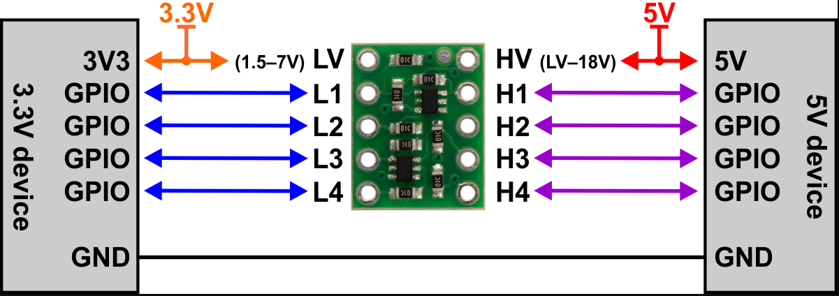
Be aware that ESP MCU is 3.3V on GPIO pin and some target board can be 3.3V and others 5V, so you may not be able to directly connect ESP board to target board.
Disclaimer : this wiki is for reference - you are responsible of your board supporting or not 5V, we are not responsible for any damage of wrong wiring.
ESP32 and ESP8266 MCU are only supporting 3.3V. Power supply them with 5V will likelly fry them immediatelly. As MCU is supplied at 3.3V, Tx and Rx signals will be at 3.3V even when board is supplied with 5V. Wether Rx pin is supporting 5V is controversial so we will keep on the safe side and only take datahseet as reference. It’s not recommended to have any signal (including Rx) be higher than power supply (3.3V here).
There are several points to take care. One should check that
- MCU1 Tx voltage is lower than MCU2 supply voltage
- Voh_min of Tx is higher than Vih_min of Rx (to check both ways)
- Vol_max of Tx is lower than Vil_max of Rx (to check both ways)
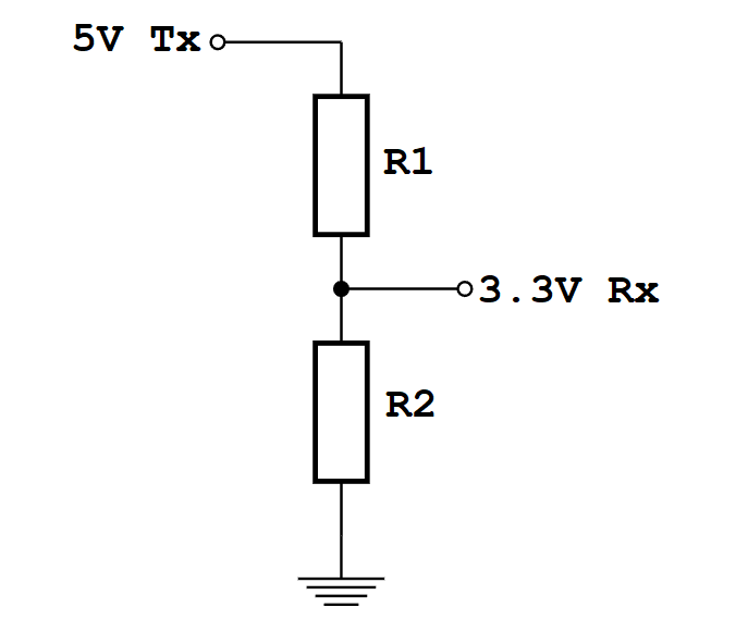
1 is mandatory and resistor voltage divider bridge or level shiffter is recommended
2 & 3 are not destructive there is just a slight risk signals are not read correctly. But it will work in most case as the limit values given by datasheets are rarelly met in mild conditions (using near 25°C and low current flowing from Tx to Rx)
For the divider bridge a value of R1=1k and R2=2.2k will be fine. You could also use 10k and 22k or anything near a factor 2.
Connection diagrams examples for some ESP boards
- ESP boards
- ESP-01
- ESP-01 serial wifi module
- ESP-12E/F
- ESP 12F serial wifi module
- ESP32-Cam
- NodeMCU V2/V3
- Sonoff
- Wemos D1 mini
ESP boards
ESP-01
- Use GPIO2 to ground to reset all settings in hard way - 2-6 sec after boot / not before!! Set GPIO2 to ground before boot change boot mode and go to special boot that do not reach FW. Currently boot take 10 sec - giving 8 seconds to connect GPIO2 to GND and do an hard recovery for settings
- Use GPIO0 to ground to be in update mode
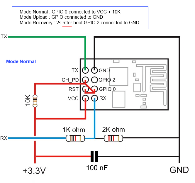
ESP-01 serial wifi module
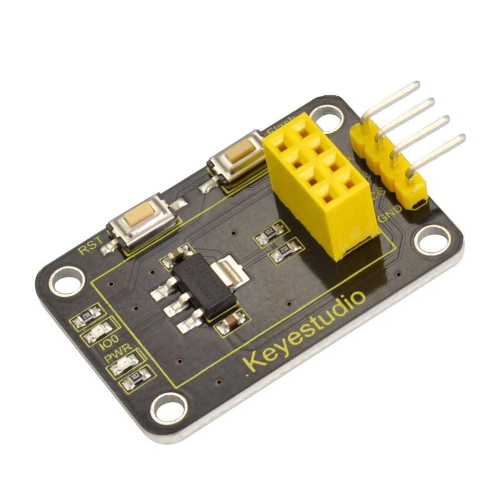
more info about the Breakout PCB: keyestudio
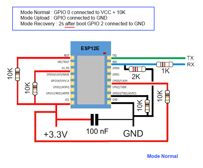
ESP-12E/F
ESP need 3.3v, it is not 5v tolerant, if printer board use more than 3.3V like 5V on ramps.
you can also use Logic LevelConverter Bi-Directional
In order to flash some ESP12E/F boards via their UART interface, the following pins need to be connected:
- VCC to GPIO2
- GND to GPIO0
This has been tested with ESP-12-E boards labeled “ESP8266 For ESP3D FYSETC.COM”
ESP 12F serial wifi module
ESP-12F based serial wifi module (eg from aliexpress ) contains built in 2-way levelshifter/bi-directional logic level converter. So it can be powered via 5V uart from the target’ motherboard.
- We need to manualy ground the
IO0while powering up to start in flash mode while powering up (there is no switch for that, neither for reset)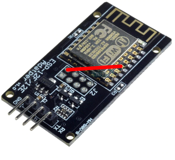
- Use FTDI adapter as usb2serial
- Need to see in console/serial monitor boot mode is (1,7).
- baudrate: 74880
rst cause:2, boot mode:(3,7)
- Then flash like other esp based board for esp3d
ESP32-Cam
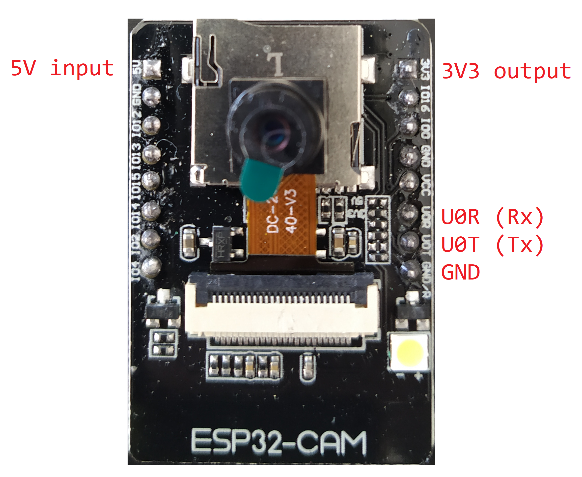
Note: 5V is power supply input and 3V3 is output from regulator. UART Tx and RX signals will be 3.3V
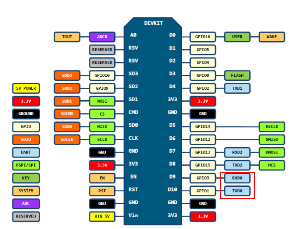
NodeMCU V2/V3
Sonoff
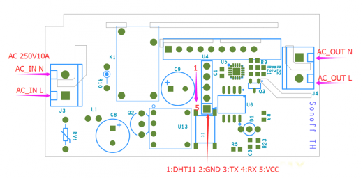
Relay is connected by GPIO12, it can be handled using ESP201 command:
*Get/Set pin value
[ESP201]P<pin> V<value> [PULLUP=YES RAW=YES]
if no V<value> get P<pin> value
if V<value> 0/1 set INPUT_PULLUP value, but for GPIO16 INPUT_PULLDOWN_16
GPIO1 and GPIO3 cannot be used as they are used for serial
if PULLUP=YES set input pull up, if not set input
if RAW=YES do not set pinmode just read value
So [ESP201]P12 V0 should be off and [ESP201]P12 V1 should be on
Wemos D1 mini
Connection with logic level conveter:
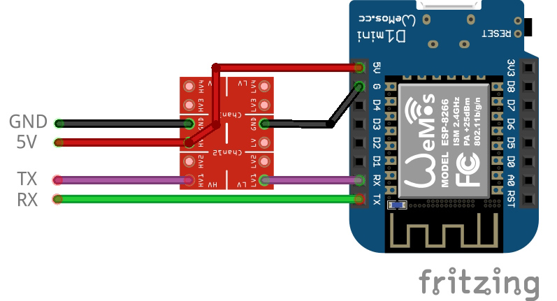
example:
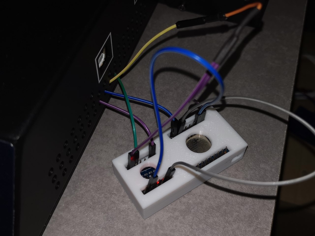
printed cases: