ESP3D-X Firmware for PiBot Pendant - User Documentation
Section titled “ESP3D-X Firmware for PiBot Pendant - User Documentation”This document provides a comprehensive guide to all screens available in the ESP3D-X Firmware for PIBot Pendant for FluidNC/GRBL CNC machines.
Version 2.0.0a13+ — May 2026

Table of Contents
Section titled “Table of Contents”Overview
Section titled “Overview”The ESP3D-X Pendant provides a touchscreen interface for controlling CNC machines running FluidNC or GRBL firmware. It combines multiple input methods to offer a versatile and efficient control experience, whether you prefer touch interaction or physical controls.
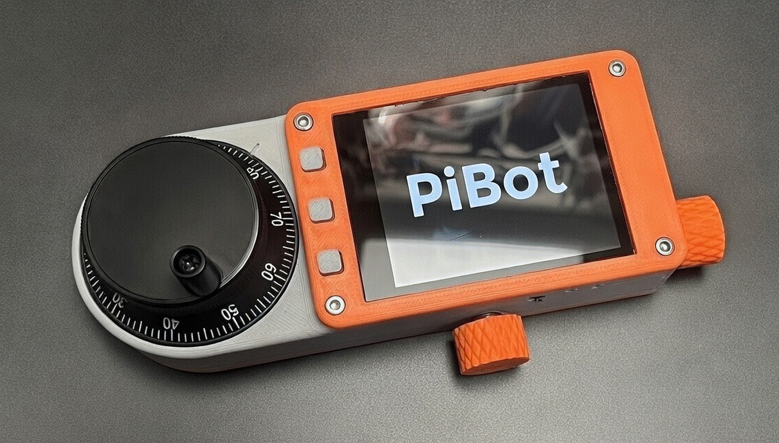
Pendant Overview
Key Features:
- Touchscreen display with rotatable interface
- Multiple physical input controls (buttons, encoder, switch, potentiometer)
- Bluetooth and Serial connectivity to CNC firmware
- SD card support for firmware updates and configuration
- Battery-friendly power management
User Interface
Section titled “User Interface”Screen Layout
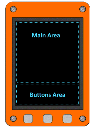
Section titled “Screen Layout”The pendant display is divided into two main areas:
|  | | Zone | Size | Description |
|:-----|:-----|:------------|
| Main Area (1) | 240 × 240 px | Primary content area displaying screens, menus, and controls |
| Button Area (2) | 80 × 240 px | Virtual buttons mirroring the physical buttons below the screen | |
|---|---|
| | Zone | Size | Description |
|:-----|:-----|:------------|
| Main Area (1) | 240 × 240 px | Primary content area displaying screens, menus, and controls |
| Button Area (2) | 80 × 240 px | Virtual buttons mirroring the physical buttons below the screen | |
|---|---|
Screen Rotation:
The entire display (both zones) can be rotated by 90°, 180°, or 270° in the Settings to accommodate different mounting orientations. The rotation applies to the complete 320 × 240 display area.
 Rotation 0° Rotation 0° | 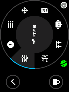 Rotation 90° Rotation 90° | 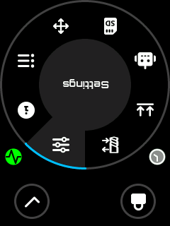 Rotation 180° Rotation 180° | 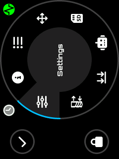 Rotation 270° Rotation 270° |
|---|
Virtual Buttons:
The button area displays 0 to 3 virtual buttons depending on the current context. These buttons mirror the physical buttons and provide visual feedback when pressed. Common ones are:
When the middle button displaying:
Switch button
User when pressing it, to change the side buttons, allowing more actions than the number of physical available buttons . These additional actions can be assigned depending on screen and context. The buttons can also be disabled according context / firmware state.
Input Methods
Section titled “Input Methods”The pendant offers five input methods that work together to provide efficient control:
| 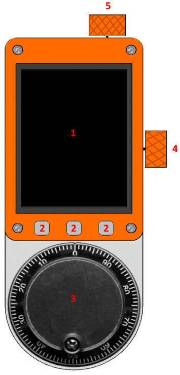 | | # | Control | Location | Description |
|:-:|:--------|:---------|:------------|
| 1 | Touchscreen | Display surface | Direct interaction with UI elements. Tap buttons, scroll lists, and select items |
| 2 | Physical Buttons | Between screen and encoder | 3 buttons for navigation, selection, and quick actions. Mirrored on screen as virtual buttons |
| 3 | Rotary Encoder | Below the buttons | Rotate for navigation in lists, value adjustment, or sending successive commands. Press for selection |
| 4 | 4-State Switch | Right side, below power button | Rotary switch for context-sensitive selection: view modes, active axis, or operation modes |
| 5 | Potentiometer | Top right, near USB and RJ11 ports | Analog control that enables different action modes based on its position | |
|---|---|
| | # | Control | Location | Description |
|:-:|:--------|:---------|:------------|
| 1 | Touchscreen | Display surface | Direct interaction with UI elements. Tap buttons, scroll lists, and select items |
| 2 | Physical Buttons | Between screen and encoder | 3 buttons for navigation, selection, and quick actions. Mirrored on screen as virtual buttons |
| 3 | Rotary Encoder | Below the buttons | Rotate for navigation in lists, value adjustment, or sending successive commands. Press for selection |
| 4 | 4-State Switch | Right side, below power button | Rotary switch for context-sensitive selection: view modes, active axis, or operation modes |
| 5 | Potentiometer | Top right, near USB and RJ11 ports | Analog control that enables different action modes based on its position | |
|---|---|
Control Usage by Context:
| Control | Main/Settings | Jog | Status | SD/Macros |
|---|---|---|---|---|
| Touchscreen | Menu selection | Tap axis buttons | Tap overrides | File selection |
| Buttons | Navigate/Select | Jog +/- | Navigate views | Navigate/Select |
| Encoder | Scroll menus | Jog by steps | Scroll views | Scroll file list |
| Switch | - | Select axis | Select position display | Select mode |
| Potentiometer | - | - | Select detail view | - |
Audio Feedback
Section titled “Audio Feedback”The pendant provides audio feedback for user interactions:
- Button press - Confirmation beep
- Selection - Distinct tone for selections
- Errors/Warnings - Alert sounds for important notifications
- Navigation - Subtle feedback when scrolling
Audio feedback can be enabled or disabled in the Settings Screen.
Power Management
Section titled “Power Management”To preserve battery life and extend screen longevity, the pendant includes an automatic screen timeout feature:
- After a configurable period of user inactivity, the screen backlight turns off automatically
- Any user interaction (touch, button press, encoder rotation, change switch state, use potentiometer) wakes up the screen
- The timeout duration can be configured or disabled entirely in the Time Out Screen
Communication Methods
Section titled “Communication Methods”The pendant can communicate with CNC firmware through several methods:
Built-in Communication:
| Method | Description |
|---|---|
| Serial | Wired connection via RJ11 port to the CNC controller |
| Bluetooth Serial | Classic Bluetooth wireless connection (SPP profile) |
| Bluetooth BLE | Bluetooth Low Energy wireless connection |
| WiFi and Socket TCP | Wireless TCP connection to a CNC controller running a Telnet/socket server |
External Module (via Serial input):
| Method | Description |
|---|---|
| External Module | External BT/BLE or other module connected via the UART extension port |
WiFi limitations: Only the Socket TCP mode is supported. WebSocket client, WebUI (HTTP server), WebDAV, etc… are not supported in the pendant build — they are unnecessary for a CNC pendant and would consume too much RAM and MCU cycles on the ESP32.
Note: The communication method can be changed in the Output Selector Screen. A restart is required after changing the output method.
SD Card Updates
Section titled “SD Card Updates”The SD card can be used to update the pendant firmware or restore user settings:
| File | Purpose |
|---|---|
esp3dfw.bin | Firmware update file |
esp3dcnf.ini | Settings configuration file |
Update Process:
- Copy the update file(s) to the SD card root directory
- Insert the SD card and power on the pendant
- The Update Screen appears automatically
- Follow the on-screen instructions
⚠️ Firmware Update Limitations:
The SD card update only flashes the firmware partition. It does not update:
- The bootloader
- The partition table
This means the
esp3dfw.binfile must be compatible with the current ESP-IDF version and partition layout already installed on the device.For a complete update (including bootloader and partition table), use the Web Installer or perform a manual flash via USB.
See the Update Screen section for detailed behavior and status indicators.
For the configuration file format, see Configuration File Reference in the Appendix.
Navigation Flow
Section titled “Navigation Flow”Global Navigation Diagram
Section titled “Global Navigation Diagram”Screen Descriptions
Section titled “Screen Descriptions”Update Screen
Section titled “Update Screen”The Update screen appears automatically when firmware update files are detected on the SD card at startup.
Hardware Controls: Touch, Buttons
Supported Files:
esp3dfw.bin- Firmware updateesp3dcnf.ini- Settings configuration
Behavior:
- On success: File renamed to
.okextension, automatic restart - On failure: File renamed to
.badextension, user confirmation required before restart - When both files are present: Firmware update applies first, then settings update after restart
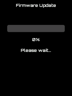 | 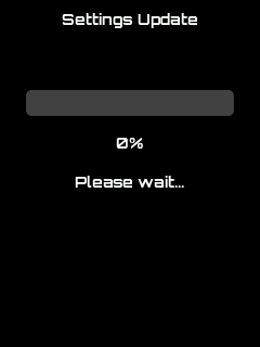 | 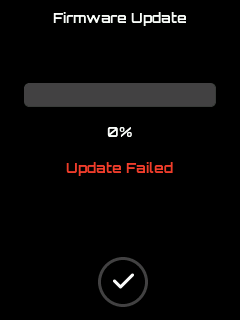 |
|---|---|---|
| Firmware update in progress | Settings update in progress | Update failed |
Splash Screen
Section titled “Splash Screen”A brief information screen displaying firmware details. Automatically transitions to the Main screen after a few seconds while core features initialize in the background.
Hardware Controls: None (automatic transition)
 Splash Screen Splash Screen |  Splash Screen Splash Screen |
|---|
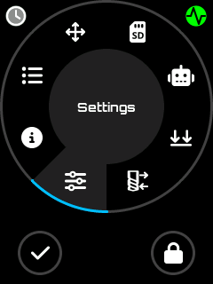
Main Screen
Section titled “Main Screen”The central hub of the pendant featuring a circular menu for task selection.
Hardware Controls: Touch, Buttons, Encoder
Features:
- Circular navigation menu for screen selection
Main Screen
- Clickable firmware status indicator (open Firmware Status screen)
- Clickable connection indicator (open Connection Status detailed informations)
- UI lock/unlock toggle to prevent accidental inputs
When locked (user choice or no connection), only the following screens are accessible:
- Information
- Status
- Settings
Main Screen
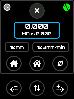
When unlocked, all screens are accessible:
Main Screen Unlocked
Note: Some screens are optionally displayed - user can show/hide: Tool Change, Macros, and Probe screens.
Connection Status icon/Screen
Section titled “Connection Status icon/Screen”The connection status icon is displayed on the Main screen and other screens. Tapping it opens the Connection Status screen.
Status icons:
Hardware Controls: Touch, Buttons
Display:
The Connection Status screen shows a color-coded title bar and detailed transport information:
| Title Bar Color | State | Meaning |
|---|---|---|
| Green | Connected | Transport and CNC server both connected |
| Blue | Connecting | Connection in progress (spinner shown) |
| Orange | Auth Failed / Read-only | Wrong credentials, or connected read-only |
| Red | Not Connected | Transport disconnected |
| Grey | Radio Off | Radio disabled |
The screen always shows:
- Transport protocol (Serial, Socket-TCP, Bluetooth, External Module)
- Network layer (WiFi: SSID) — WiFi mode only, orange when WiFi is down
- Device info (CNC host:port, BT device name + MAC, or serial baud rate)
- Animated spinner — visible only while connecting
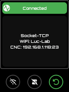
Connection Status Screen
Button 0 (LEFT) — Transport action:
Depends on transport type and current state:
| Transport | State | Icon | Action |
|---|---|---|---|
| WiFi | WiFi down | (disabled) | |
| WiFi | Not connected / disconnected | Reconnect WiFi | |
| WiFi | Connected | Disconnect WiFi | |
| WiFi | Auth failed | Open password input to correct credentials | |
| Serial | Not connected | Reconnect serial | |
| Serial | Connected | Disconnect serial | |
| Ext. Module | Not connected | Reconnect external module | |
| Ext. Module | Connected | Disconnect external module | |
| Bluetooth | Not connected | Connect Bluetooth | |
| Bluetooth | Connected | Disconnect Bluetooth | |
| Bluetooth | Auth failed | Open PIN input to correct Bluetooth PIN/passkey |
Button 1 (CENTER) — IP CNC action (WiFi + Socket TCP builds only):
| State | Icon | Action |
|---|---|---|
| Not connected | Connect to CNC socket server | |
| Connected / Connecting | Disconnect from CNC server | |
| Auth failed | Correct server credentials | |
| WiFi down | (disabled) | — |
For Serial and External Module outputs, Button 1 shows a Refresh icon (
) when connected — tapping it resends initialisation commands to the CNC.
Button 2 (RIGHT) — Back: Returns to calling screen.
WiFi auth-fail unlock flow:
When the WiFi status is Auth Failed (wrong password):
- The title bar turns orange and Button 0 shows the
 icon
icon - Tap Button 0 → a password input screen opens, pre-filled with the saved password
- Edit the password and press OK → new password is saved, connection is retried
- Press Cancel → return to the WiFi scan screen without retrying
Bluetooth auth-fail / PIN change:
When Bluetooth connection shows Auth Failed:
- Button 0 shows the icon
- Tap Button 0 → a PIN input screen opens (4 digits for BT Classic, 6 for BLE)
- Enter the correct PIN → bonded devices are cleared and connection is retried
Serial/WiFi retry behaviour:
When WiFi fails after 10 retries or when the SSID is not found, the state changes to Not Connected. Press Button 0 to start a new connection cycle.
Firmware Status icon/Screen
Section titled “Firmware Status icon/Screen”Firmware Status Icon with unknown status
Status Icons:
| Status | Icon | Description |
|---|---|---|
| Unknown | Waiting for system report | |
| IDLE | Machine ready | |
| RUN | Program executing | |
| ALARM | Alarm condition active | |
| CHECK | Check mode | |
| DOOR | Door open | |
| HOLD | Feed hold active | |
| HOME | Homing in progress | |
| SLEEP | Sleep mode | |
| JOG | Jogging in progress | |
| TOOL | Tool change in progress | |
| ERROR | Error condition |
Real-time firmware state monitoring and control, accessible by tapping the status indicator on compatible screens.
Hardware Controls: Touch, Buttons, Encoder (scrolls message history)
Display:
- Current firmware state
- Scrollable list of the last 20 messages
- Message color coding: Red = Error, Blue = Info
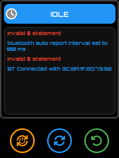
Firmware Status Screen
Available Commands by State:
| State | Primary Action | Icon | Secondary Action | Icon |
|---|---|---|---|---|
| ALARM | Unlock ($X + ?) | Soft Reset (0x18 + ?) | ||
| HOLD | Resume (~) | Refresh (?) | ||
| RUN | Feed Hold (!) | Refresh (?) | ||
| JOG | Stop Jog (0x85) | Refresh (?) | ||
| IDLE | Soft Reset (0x18 + ?) | Refresh (?) | ||
| ERROR | Soft Reset (0x18 + ?) | Refresh (?) | ||
| Others | Soft Reset (0x18 + ?) | Refresh (?) |
Information Screen
Section titled “Information Screen”Information Icon
Displays firmware and system details.
Hardware Controls: Touch, Buttons
Content displayed:
| Field | Description |
|---|---|
| Version | ESP3D-X firmware version |
| Target Firmware | CNC firmware name and version (FluidNC / grblHAL) |
| Communication | Active output (Serial, WiFi Socket-TCP, Bluetooth, External Module…) |
| Board / Machine | Target board name |
| UI Language | Active language pack |
| Lock State | Locked / Unlocked |
| Axis Count | Number of configured CNC axes |
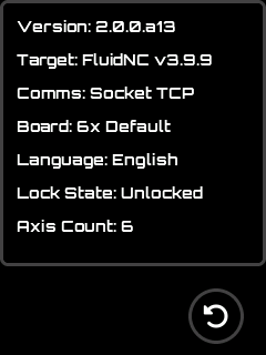
Information Screen
Status Screen
Section titled “Status Screen”Status Icon
Provides a global overview of the CNC machine state.
Hardware Controls: Touch, Buttons, Switch, Encoder, Potentiometer
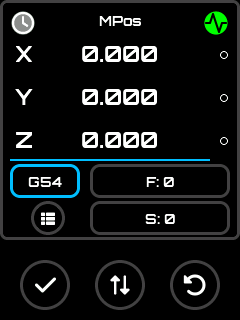
Position Display Modes (selected via 4-state switch):
- Machine Position (MPos)

Status Screen MPos Mode
- Work Position (WPos)
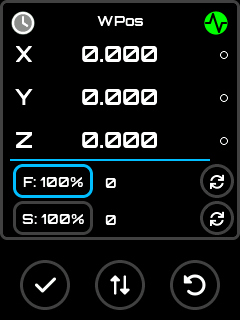
Status Screen WPos Mode
- Both MPos & WPos
Status Screen MPos & WPos Mode
- UI Lock Mode
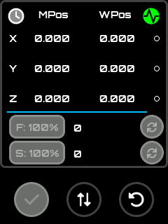
Status Screen Locked Mode
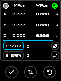
Detail Views (selected via potentiometer):
- Feed rate and spindle override controls
Override view
- Rapid override controls
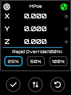
Rapid override view
- Control Spindle state / Coolant Actions
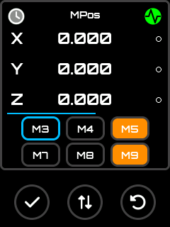
Control view
- Workspace selector, G-code status, feed/spindle controls
 Workspace view Workspace view | 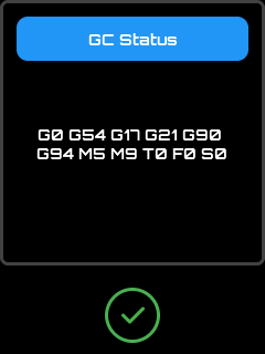 GC Status GC Status |
|---|
- SD card job progress
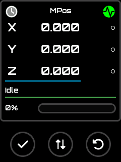
Job view
- Fast access to Stop / Pause / Resume buttons
To have better control on job progression, the buttons mode can be switched to stop/pause or stop/resume according firmware state context anytime by using the middle button.
Additional Features:
- Real-time endstop state display
- Clickable firmware status indicator (open Firmware Status screen)
- Clickable connection indicator (open Connection Status detailed informations)
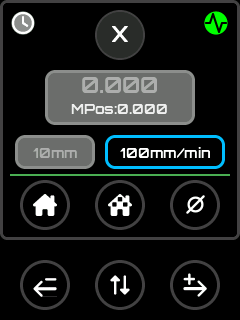
Jog Screen
Section titled “Jog Screen”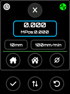 Jog Screen Jog Screen | 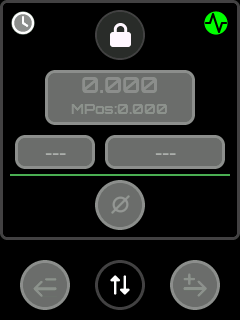 Jog Screen Locked Jog Screen Locked |
|---|
Manual machine movement control with multiple input options.
Hardware Controls: Touch, Buttons, Switch, Encoder
Axis Selection (via 4-state switch):
- 3-axis machines: X, Y, Z, + Lock mode
- 4-6 axis machines: X, Y, Z, + Button axis selector
Jog Modes:
- Step mode - Discrete movements via encoder or buttons
Discrete Jog screen
- Continuous mode - Sustained movement while button held
Continuous Jog screen
Features:
- Configurable step sizes and feed rates
- Endstop state display (when enabled)
- Zero axis function
- Home per axis or all axes (depending on firmware configuration)
- Real-time position display
Additional Features:
- Real-time endstop state display
- Clickable firmware status indicator (open Firmware Status screen)
- Clickable connection indicator (open Connection Status detailed informations)
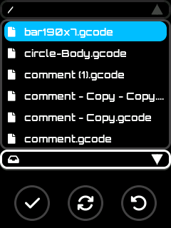
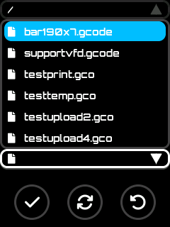
SD Screen
Section titled “SD Screen”SD Icon
File browser for the CNC firmware’s SD card.
Hardware Controls: Touch, Buttons, Switch, Encoder
Operation Modes (selected via 4-state switch):
Features:
- Manual refresh of file list
- File extension filtering (configurable in settings)
| Mode | Icon | Description |
|---|---|---|
| Process | Process selected file as a job | |
| Informations / Add Macro (if macros enabled in settings) | Display file informations and Assign/Remove file as a macro for quick access | |
| Informations (if macros not enabled in settings) | Display file informations | |
| Rename | Rename the selected file | |
| Delete | Remove file from SD card |
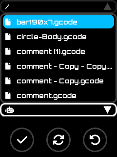
Process mode
SD Screen Process Mode
Using set button start processing file if user confirm action
Processing Confirmation
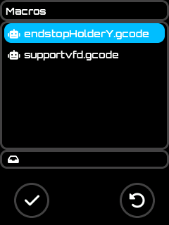
Informations / Add Macro Mode (if macros enabled in settings)
Assign / Remove macro Mode
Using set button display informations screen where user can assign/remove file as a macro
 Add File to macros list Add File to macros list | 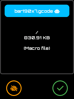 Remove File from macros list Remove File from macros list |
|---|
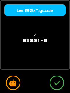
Informations Mode (if macros not enabled in settings)
Informations Mode
Using set button display file informations screen
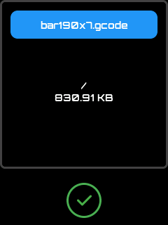
File Informations
Rename Mode
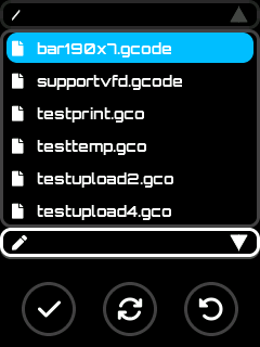
Rename Mode
Using set button display input editor screen to rename file or cancel action
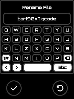
Input Editor for renaming
Delete Mode
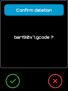
Delete Mode
Using set button delete file if user confirm action
Delete Confirmation
Macros Screen
Section titled “Macros Screen”Macros Icon
Quick access to assigned macro files for frequently used operations.
Hardware Controls: Touch, Buttons, Switch, Encoder
Operation Modes (selected via 4-state switch):
| Mode | Icon | Description |
|---|---|---|
| Process | Execute the macro | |
| Rename | Change macro display name (does not affect actual file name) | |
| Reorder | Change macro position in list | |
| Remove | Remove from macro list (includes clear all option) |
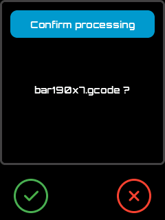
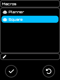
Process Mode
 Macros Screen no description edited Macros Screen no description edited | 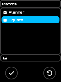 Macros Screen with descriptions Macros Screen with descriptions |
|---|
Using set button start processing macro file if user confirm action
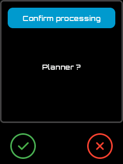
Confirm Processing
Rename Mode
Rename Mode
Using set button display input editor screen change file description or cancel action
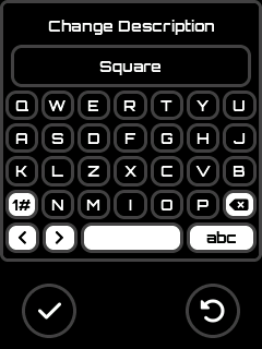
Change Description
Reorder Mode
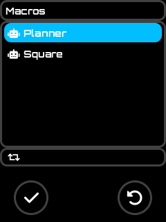
Reorder Mode
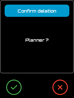
Delete Mode
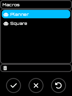
Delete Mode
Using set button remove selected file from macros list if user confirm
Delete Mode
Using clear button clear the full macros list if user confirm
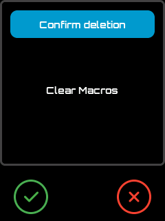
Delete Mode
Probe Screen
Section titled “Probe Screen”Probe Icon
Axis probing interface for tool measurement and workpiece setup.
Hardware Controls: Touch, Buttons, Switch, Encoder
Features:
- Per-axis probe configuration
- Automatic saving of probe settings per axis
- Integration with Change Tool workflow
- Clickable firmware status indicator (opens Firmware Status screen)
- Clickable connection indicator (open Connection Status detailed informations)
Axis Selection (via 4-state switch):
- 3-axis machines: X, Y, Z, + Lock mode
- 4-6 axis machines: X, Y, Z, + Button axis selector
 Probe Screen Probe Screen |  Locked State Locked State |
|---|
Probe Operation Flow
Section titled “Probe Operation Flow”Change Tool Screen
Section titled “Change Tool Screen”Change Tool Icon
Guided tool change procedure compatible with FluidNC and grblHAL settings.
Hardware Controls: Touch, Buttons, Encoder
Features:
- Current tool display and selection
- Manual tool change guidance
- Optional integrated probe workflow
- Clickable firmware status indicator (open Firmware Status screen)
- Clickable connection indicator (open Connection Status detailed informations)
Tool Change Flow with Optional Probe
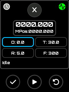
Section titled “Tool Change Flow with Optional Probe”- Set current tool if not done and apply by pressing play, or go to 3 directly
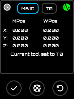
Set current Tool
- Press Play and process probing if necessary or ignore it
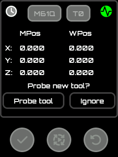
Probe Current tool
- Switch to Change tool mode
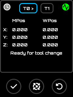
Set Current Tool
- Select new tool using input editor
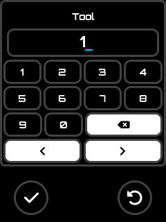
Set New Tool Index
- Press Play and Follow manual change procedure
- (Optional) Probe new tool length
- Confirm tool change
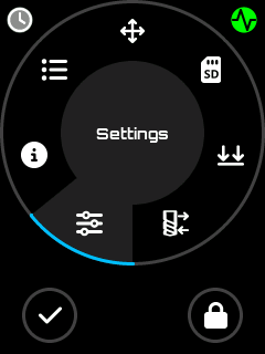
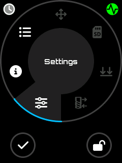
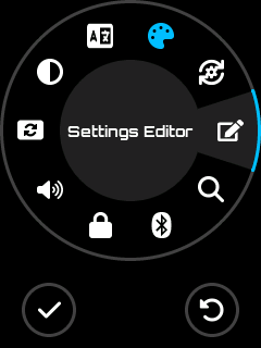
Settings Screen
Section titled “Settings Screen”Settings Icon
Comprehensive configuration interface for customizing the pendant behavior.
Hardware Controls: Touch, Buttons, Encoder, Virtual Hardware
Access to:
- Reset Settings
- Theme selection
- Language selection
- Backlight level
- Orientation selection
- Sound control
- Lock button display
- Output selector (communication method)
- Bluetooth Serial
- Bluetooth Ble
- Serial
- Output mode configuration:
- Bluetooth scanning
- Baudrate configuration
- Additional settings list
See Settings Reference for the complete list of available settings.
Settings Screen
Reset Settings
Section titled “Reset Settings”Reset Settings Icon
Hardware Controls: Touch, Buttons
This will reset all setting to their default state, a restart is mandatory to be properly applied.
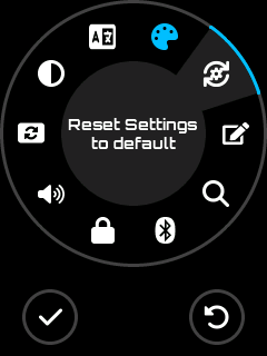
Reset Settings menu
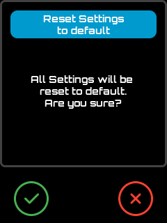
Apply Reset Confirmation
Theme Selection
Section titled “Theme Selection”Theme Icon
Hardware Controls: Touch, Buttons, Encoder
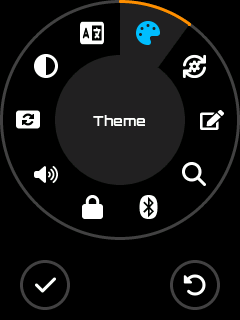
This allow to change the color scheme of the UI.
1 - Go tho theme menu
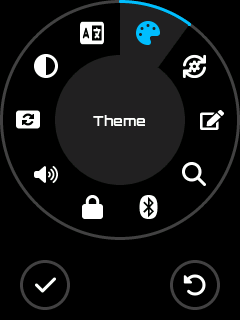
Theme Menu
2 - Activate the setting selection pressing menu or set button
Activate Theme Selector
3 - Change theme using encoder
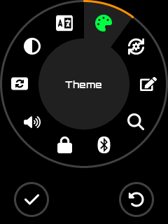
Change Theme
4 - Choose theme by pressing menu or set button

Apply Theme
Setting is saved automaticaly when you press menu or set button, if you press cancel button instead of set button, operation is canceled.
Languages Screen
Section titled “Languages Screen”Languages Icon
Language pack selection for the UI.
Hardware Controls: Touch, Buttons, Encoder
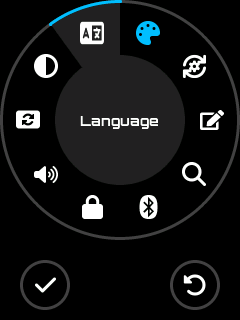
Languages Menu
Features:
- Lists all available language packs from SD card
- Immediate language switching
Note: The language pack file must be present on the SD card at startup to be loaded.
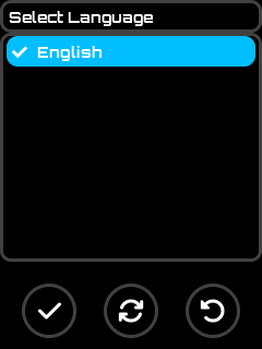
Languages Screen
Backlight level
Section titled “Backlight level”Backlight Icon
Change the level of screen backlight.
Hardware Controls: Touch, Buttons, Encoder
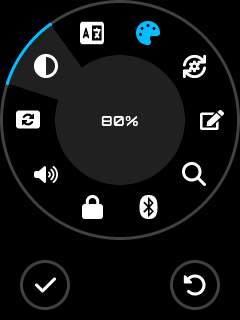
Backlight Menu
Once menu activated, the backlight level can be changed using encoder from 0% to 100%
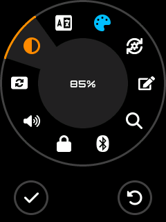
Backlight Level Modification
Setting is saved automaticaly when you press menu or set button, if you press cancel button instead of set button, operation is canceled.
Orientation selection
Section titled “Orientation selection”Orientation Icon
Change the screen orientation by 0, 90 , 180 and 270 angular degres.
Hardware Controls: Touch, Buttons, Encoder
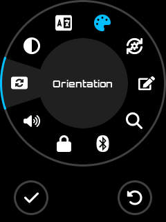
Orientation Menu
Once menu activated, the orientation can be changed using encoder.
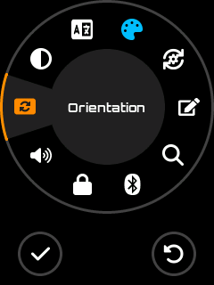 0 degrees 0 degrees | 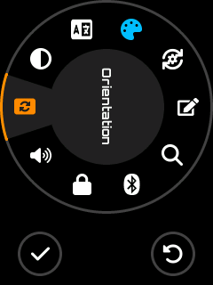 90 degrees 90 degrees |
|---|
Setting is saved automaticaly when you press menu or set button, if you press cancel button instead of set button, operation is canceled.
Sound control
Section titled “Sound control”Enable or Mute Sound by toggle, the displayed icon represent the current state.
Hardware Controls: Touch, Buttons
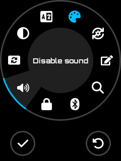 Mute Menu Mute Menu |  Enable Menu Enable Menu |
|---|
Setting is saved automaticaly when you press menu or set button.
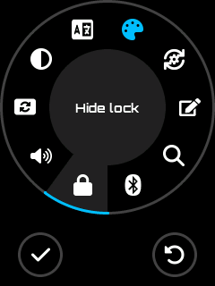
Lock button display
Section titled “Lock button display”Allow to show / hide the lock control, the icon displayed represent the current state
Hardware Controls: Touch, Buttons
| Hide Lock UI Control | 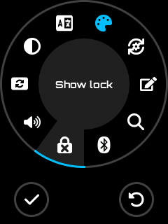 Show Lock UI Control Show Lock UI Control |
|---|
Setting is saved automaticaly when you press menu or set button.
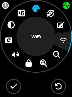
Output Selector Screen
Section titled “Output Selector Screen”Communication method selection. The menu icon shows the currently active mode.
Hardware Controls: Touch, Buttons, Encoder
Available Options:
| Option | Description |
|---|---|
| Serial | Wired connection via RJ11 port |
| Bluetooth Serial | Classic Bluetooth SPP |
| Bluetooth BLE | Bluetooth Low Energy |
| WiFi Socket TCP | Wireless TCP/telnet connection to a CNC controller (if WiFi build) |
| External Module | External BT/BLE or other UART module (if Ext Module build) |
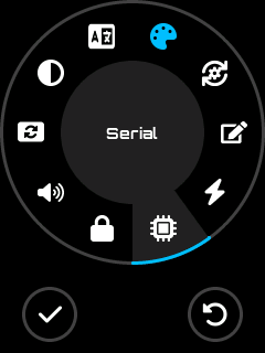 Serial selected Serial selected | 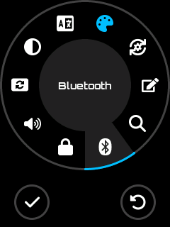 BT Serial selected BT Serial selected |
|---|---|
 WiFi selected WiFi selected | 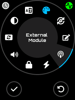 Ext Module selected Ext Module selected |
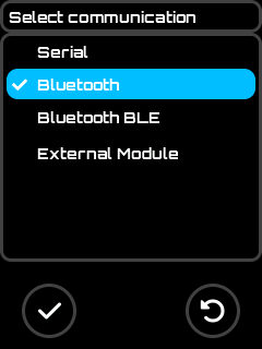 Output Selection Screen(BT Firmware) Output Selection Screen(BT Firmware) | 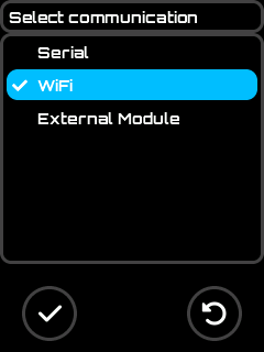 Output Selection Screen(WiFi Firmware) Output Selection Screen(WiFi Firmware) |
|---|
Note: A restart is required after changing the output method. A confirmation message will be displayed.
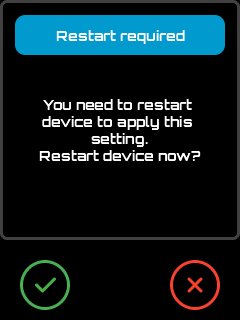
Restart Confirmation
Output mode configuration
Section titled “Output mode configuration”The configuration icon in the Settings screen adapts to the active output mode:
| Active Output | Configuration Icon | Opens |
|---|---|---|
| Serial | Baudrate Screen | |
| BT Serial / BT BLE | Scan Bluetooth Screen | |
| WiFi (WiFi Part 1) | WiFi Scan Screen | |
| Socket TCP (WiFi Part 2) | Scan Server | |
| External Module | Baudrate Screen (Ext module baud) |
WiFi — Two-step connection model:
WiFi mode requires two separate connection steps, unlike Serial or Bluetooth where a single connection reaches the CNC controller directly.
Step Action Screen 1 Connect the pendant to a WiFi access point (the network transport) WiFi Scan Screen → selects the AP and saves credentials 2 Connect to the CNC controller’s TCP socket server (the CNC link) Server Scan Screen → selects the host:port; or use Button 1 in Connection Status WiFi is only the remote communication layer — it replaces the cable. The actual CNC link is the TCP socket connection in step 2. Both steps must succeed for the pendant to communicate with the CNC.
Hardware Controls: Touch, Buttons, Encoder
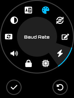 Baudrate (Serial) Baudrate (Serial) | 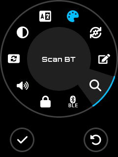 Scan BT (BT BLE) Scan BT (BT BLE) |
|---|---|
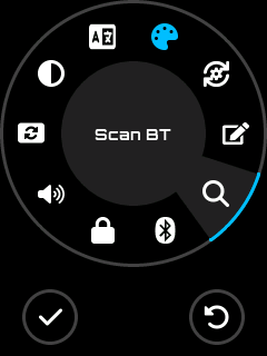 Scan BT (BT Serial) Scan BT (BT Serial) | 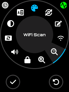 WiFi Scan WiFi Scan |
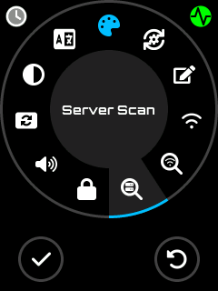 Scan Server (WiFi) Scan Server (WiFi) | 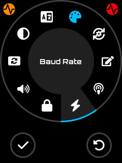 Baudrate (External Module) Baudrate (External Module) |
Baudrate Screen
Section titled “Baudrate Screen”Baudrate Icon
Serial communication speed configuration.
Hardware Controls: Touch, Buttons, Encoder
Visibility: Available when current output is Serial or External Module
Features:
- Select from available baud rates
- Changes apply immediately
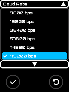
Baudrate Screen
Scan Bluetooth Screen
Section titled “Scan Bluetooth Screen”Scan Bluetooth Icon
Bluetooth device discovery and pairing.
Hardware Controls: Touch, Buttons, Encoder
Visibility: Only available when current output is Bluetooth Serial or Bluetooth BLE
Features:
- Scan for available Bluetooth devices (up to 30 s)
- Select and pair with a device
- Save target BT host for automatic connection on subsequent startups
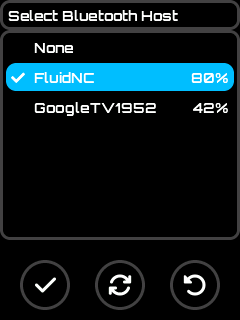
Scan Bluetooth Screen
Bluetooth PIN / Passkey:
If the CNC controller requires a PIN (BT Classic) or passkey (BLE), you will be prompted on the Connection Status Screen when connection fails with Auth Failed. Tap the ![]() button to enter or correct the PIN.
button to enter or correct the PIN.
- BT Classic: 4-digit PIN
- BLE: 6-digit passkey
- Empty = no authentication (SEC_NONE)
WiFi Scan Screen
Section titled “WiFi Scan Screen”WiFi access point discovery and credential configuration.
Step 1 of 2 — Network transport only. This screen connects the pendant to a WiFi network. After this step the pendant has network access, but it is not yet connected to the CNC controller. Proceed to the Server Scan Screen (step 2) to establish the CNC socket link.
Hardware Controls: Touch, Buttons, Encoder
Visibility: Only available when current output is WiFi
Features:
- Asynchronous scan (UI stays responsive during scan)
- APs sorted by signal strength (strongest first)
- Signal percentage displayed for each AP
- Lock icon
 for password-protected networks
 - Checkmark for currently configured SSID
- Scan results reused when returning from password input (no re-scan needed)
Buttons:
| Button | Icon | Action |
|---|---|---|
| Select / OK | Connect to selected AP | |
| Refresh | Restart scan | |
| Back | Return to Settings |
| Scan results | 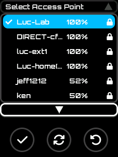 AP List AP List | 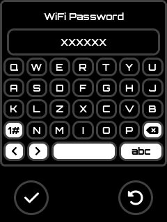 Password entry Password entry |
|---|
Selection flow:
- Select an AP from the list and press OK (or tap the item)
- Open network: SSID saved, connection starts immediately → navigates to Connection Status
- Protected network: Password input opens (pre-filled with saved password)
- Press OK → saves password, starts connection → navigates to Connection Status
- Press Cancel → returns to scan results (no reconnect attempt)
Server Scan Screen
Section titled “Server Scan Screen”TCP server discovery and selection.
Step 2 of 2 — CNC socket link. This screen connects the pendant to the CNC controller’s TCP socket server (telnet/Telnet port). The pendant must already be connected to a WiFi network (WiFi Scan Screen, step 1) before using this screen. Once a server is selected the pendant establishes the actual CNC communication link.
Hardware Controls: Touch, Buttons, Encoder
Visibility: Only available when current output is WiFi
Features:
- Asynchronous scan (UI stays responsive during scan)
- Search using mDNS telnet service availability
- Checkmark for currently selectected server
Buttons:
| Button | Icon | Action |
|---|---|---|
| Select / OK | Connect to selected AP | |
| Refresh | Restart scan | |
| Back | Return to Settings |
| Scan Server | 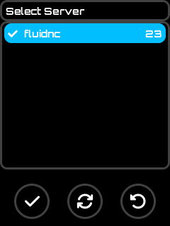 Servers List Servers List |
|---|
Selection flow:
- Select an AP from the list and press OK (or tap the item)
- Open network: SSID saved, connection starts immediately → navigates to Connection Status
- Protected network: Password input opens (pre-filled with saved password)
- Press OK → saves password, starts connection → navigates to Connection Status
- Press Cancel → returns to scan results (no reconnect attempt)
Settings List Screen
Section titled “Settings List Screen”Settings List Icon
Additional UI and hardware configuration options menu.
Hardware Controls: Touch, Buttons, Encoder
Provides Access to:
- Polling interval configuration
- Screen timeout settings
- Files extensions list
- Show/Hide Macro menu
- Show/Hide Probe menu
- Show/Hide Change Tool menu
- Enable/Disable the bypass of safety focus
- X~C axis list of usable steps for jog
- X~C axis list of usable feedrate for jog
- Enable/Disable the Rx/Tx swap
Settings Editor menu
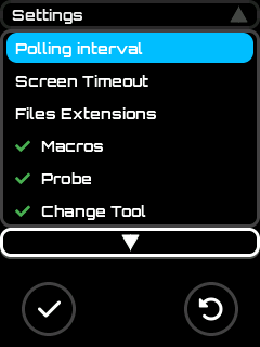
Settings Editor List
Polling Screen
Section titled “Polling Screen”Polling Interval
Configure the automatic status reporting interval.
Hardware Controls: Touch, Buttons, Encoder
Usage:
- FluidNC: Auto-report time
- grblHAL: Polling period
For FluidNC it configure the Autoreporting interval which is set when the firmware confirm communication with FluidNC. Set 0 disable the autoreporting request and use existing one if setup.
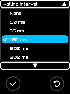
Polling Interval Screen
Note: The pendant need periodical report to display up to date informations, if you disable it in pendant, please ensure there are frequent update from firmware to maintain UI consistency.
Timeout Screen
Section titled “Timeout Screen”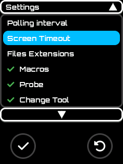
Timeout Screen
Screen backlight auto-power-off configuration.
Hardware Controls: Touch, Buttons, Encoder
Features:
- Select inactivity timeout duration from predefined list
- Option to disable auto-power-off entirely
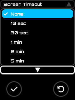
Timeout Screen
Files Extensions Screen
Section titled “Files Extensions Screen”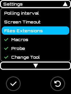
Files Extentions Menu
Edit the files extensions list used to filter usables files.
Hardware Controls: Touch, Buttons
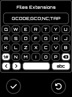
Files Extensions Editor Screen
the extensions are separated by ; and are not case sensitive.
WiFi SSID
Section titled “WiFi SSID”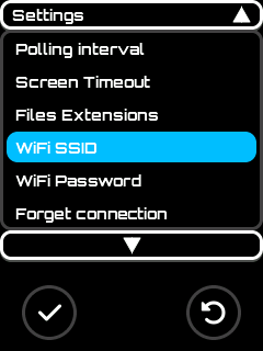
Manualy change SSID Access point
This allow to edit the WiFi Access Point SSID
Hardware Controls: Touch, Buttonson est
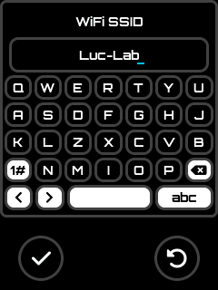
SSID Editor Screen
WiFi Password
Section titled “WiFi Password”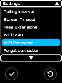
Manualy change WiFi password
This allow to edit the WiFi password
Hardware Controls: Touch, Buttons

WiFi Password Editor Screen
Forget Connection
Section titled “Forget Connection”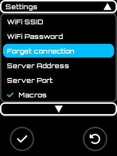
Delete all connections parameters
This allow to delete all current connection parameters: Bluetooth host, password, WiFi SSID, password, connecting server ip and port/
Hardware Controls: Touch, Buttons
The action is destructive so it request a user’s confirmation.

Confirmation Dialog
TCP Server Address
Section titled “TCP Server Address”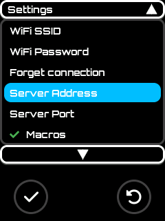
Manualy change the TCP server address
This allow to edit the WiFi TCP Socket address
Hardware Controls: Touch, Buttons
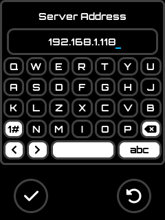
TCP Socket Server Address Editor Screen
TCP Server Port
Section titled “TCP Server Port”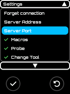
Manualy change the TCP server port
This allow to edit the WiFi TCP Socket port
Hardware Controls: Touch, Buttons
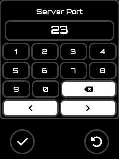
TCP Socket Server Port Editor Screen
Show / Hide Macros menu
Section titled “Show / Hide Macros menu”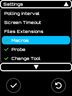
Show / Hide Macros Menu
Toggle the display of macros menu.
Hardware Controls: Touch, Buttons
Show / Hide Probe menu
Section titled “Show / Hide Probe menu”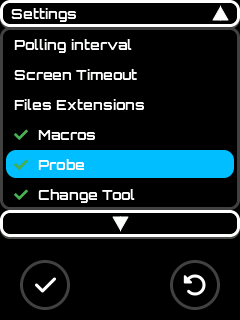
Show / Hide Probe Menu
Toggle the display of probe menu.
Hardware Controls: Touch, Buttons
Show / Hide Change Tool menu
Section titled “Show / Hide Change Tool menu”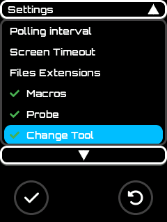
Show / Hide Change Tool Menu
Toggle the display of change tool menu.
Hardware Controls: Touch, Buttons
Enable / Disable the bypass safety
Section titled “Enable / Disable the bypass safety”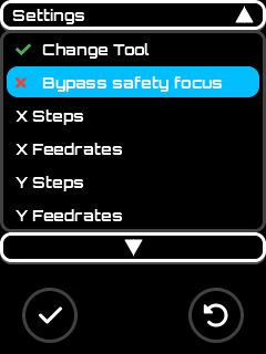
Enable / Disable The Bypass of Safety Focus Control
Toggle the Safety Focus Control. If bypass is disabled, the user need to manually enable focus on control to use (e.g: Jog). If enabled the working control got auto focus and is activated when entering screen (e.g: Jog control, user can directly use buttons / encoder to jog when entering in Jog screen).
Note: The recommendation is to keep this setting disabled.
Hardware Controls: Touch, Buttons
Edit Axis Steps List used for Jog
Section titled “Edit Axis Steps List used for Jog”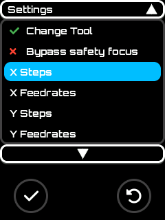
Steps List Editor Menu
Edit the steps list used by jog screen. Each axis has its own list.
Hardware Controls: Touch, Buttons
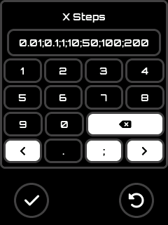
Steps List Editor Screen
the values are separated by ;
Edit Axis Feedrates List used for Jog
Section titled “Edit Axis Feedrates List used for Jog”
Feedrates List Editor Menu
Edit the steps list used by jog screen. Each axis has its own list.
Hardware Controls: Touch, Buttons
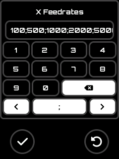
Feedrates List Editor Screen
the values are separated by ;
Enable / Disable the Rx / Tx pins
Section titled “Enable / Disable the Rx / Tx pins”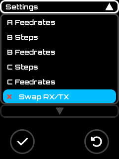
Enable / Disable Rx/Tx swap
Toggle the pins definitions used for Rx and TX in serial communications.
Hardware Controls: Touch, Buttons
Settings Reference
Section titled “Settings Reference”Complete list of available settings:
Display & UI
Section titled “Display & UI”| Icon | Setting | Description |
|---|---|---|
| Language Pack Selection | UI language | |
| Theme Selection | Visual theme | |
| Screen Orientation | Display rotation (0°, 90°, 180°, 270°) | |
| Backlight % | Screen brightness | |
| Screen Time Out | Auto-off delay |
| Icon | Setting | Description |
|---|---|---|
| Sound On/Off | Enable/disable audio feedback |
Communication
Section titled “Communication”| Icon | Setting | Description |
|---|---|---|
| Output Selector | Serial / BT Serial / BT BLE / WiFi Socket TCP / External Module | |
| Baudrate Configuration | Serial or External Module communication speed | |
| Scan Bluetooth Devices | BT device discovery and pairing | |
| WiFi Scan | WiFi AP discovery and credential setup | |
| Server Scan | TCP Socket Server discovery using mDNS (telnet) | |
| — | WiFi SSID | Stored WiFi network name (set via WiFi scan) |
| — | WiFi Password | Stored WiFi password (set via WiFi scan or unlock flow) |
| — | Hostname | Device network name (used for WiFi, mDNS) |
| Swap Rx/Tx Pins | Hardware pin configuration | |
| Polling Interval | Status update frequency |
Features Visibility
Section titled “Features Visibility”| Icon | Setting | Description |
|---|---|---|
| Show/Hide Lock Screen Control | UI lock feature | |
| Show/Hide Macros Feature | Macros screen access | |
| Show/Hide Probe Feature | Probe screen access | |
| Show/Hide Change Tool Feature | Tool change screen access |
File Management
Section titled “File Management”| Icon | Setting | Description |
|---|---|---|
| Files Extensions Filter | Visible file types in SD browser |
Safety
Section titled “Safety”| Icon | Setting | Description |
|---|---|---|
| Bypass Safety Focus | Skip safety confirmations |
Axis Configuration
Section titled “Axis Configuration”Each axis (X, Y, Z, A, B, C) has:
| Icon | Setting | Description |
|---|---|---|
| Steps Supported List | Available step increments | |
| Feedrate Supported List | Available feed rates |
System
Section titled “System”| Icon | Setting | Description |
|---|---|---|
| Reset Settings | Restore default configuration |
Appendix
Section titled “Appendix”Hardware Controls Summary
Section titled “Hardware Controls Summary”| Screen | Touch | Buttons | Switch | Encoder | Potentiometer | Virtual HW |
|---|---|---|---|---|---|---|
| Update | ✓ | ✓ | ||||
| Splash | ||||||
| Main | ✓ | ✓ | ✓ | |||
| Settings | ✓ | ✓ | ✓ | ✓ | ||
| Information | ✓ | ✓ | ||||
| Status | ✓ | ✓ | ✓ | ✓ | ✓ | |
| Jog | ✓ | ✓ | ✓ | ✓ | ||
| SD | ✓ | ✓ | ✓ | ✓ | ||
| Macros | ✓ | ✓ | ✓ | ✓ | ||
| Probe | ✓ | ✓ | ✓ | ✓ | ||
| Change Tool | ✓ | ✓ | ✓ | |||
| Firmware Status | ✓ | ✓ | ✓ | |||
| Connection Status | ✓ | ✓ | ||||
| Message Box | ✓ | ✓ | ||||
| Input Screen | ✓ | ✓ | ||||
| Languages | ✓ | ✓ | ✓ | |||
| WiFi Scan | ✓ | ✓ | ✓ | |||
| Server Scan | ✓ | ✓ | ✓ | |||
| Scan Bluetooth | ✓ | ✓ | ✓ | |||
| Baudrate | ✓ | ✓ | ✓ | |||
| Output Selector | ✓ | ✓ | ✓ | |||
| Settings List | ✓ | ✓ | ✓ | |||
| Polling | ✓ | ✓ | ✓ | |||
| Time Out | ✓ | ✓ | ✓ |
Legend:
- Touch - Touchscreen interaction enabled
- Buttons - Physical buttons active
- Switch - 4-state switch used for mode selection
- Encoder - Rotary encoder for navigation/adjustment
- Potentiometer - Analog input active
- Virtual HW - On-screen virtual hardware controls available
Screen Hierarchy Reference
Section titled “Screen Hierarchy Reference”| Screen | Parent(s) | Child Screen(s) |
|---|---|---|
| Update | - | - |
| Splash | - | Main |
| Main | Splash | Settings, Information, Status, Jog, SD, Macros, Probe, Change Tool, Message Box, Firmware Status, Connection Status |
| Settings | Main | Message Box, Languages, Settings List, Scan Bluetooth, WiFi Scan, Server Scan, Baudrate, Output Selector, Connection Status |
| Information | Main | - |
| Status | Main | Message Box, Input Screen, Firmware Status, Connection Status |
| Jog | Main | Message Box, Input Screen, Firmware Status, Connection Status |
| SD | Main | Message Box, Input Screen |
| Macros | Main | Message Box, Input Screen |
| Probe | Main, Change Tool | Message Box, Input Screen, Firmware Status, Connection Status |
| Change Tool | Main | Probe, Message Box, Input Screen, Firmware Status, Connection Status |
| Firmware Status | Main, Probe, Status, Change Tool, Jog | - |
| Connection Status | Multiple (tap icon) | Input Screen (WiFi pwd), WiFi Scan (auth-fail) |
| Message Box | Multiple | - |
| Input Screen | Multiple | - |
| Languages | Settings | - |
| WiFi Scan | Settings, Connection Status | Input Screen (password), Connection Status |
| Server Scan | Settings | Connection Status |
| Scan Bluetooth | Settings | - |
| Baudrate | Settings | - |
| Output Selector | Settings | Message Box |
| Settings List | Settings | Polling, Time Out, Input Screen |
| Polling | Settings List | - |
| Time Out | Settings List | - |
Configuration File Reference
Section titled “Configuration File Reference”The esp3dcnf.ini file allows you to configure pendant settings via SD card. Place this file on the SD card root directory, and it will be processed on boot.
File Format:
- INI format with sections in brackets
[section] - Comments start with semicolon
; - Boolean values:
yes/no,on/off,true/false,1/0 - Protected values (passwords/tokens) are replaced with
********in the.okfile after processing
Example Configuration File:
; =============================================================================; ESP3D-X Configuration File; =============================================================================;; Place this file on the SD card root as: esp3dcnf.ini; The firmware will process it on boot and rename it to esp3dcnf.ok;; Boolean values: yes/no, on/off, true/false, 1/0; Protected values (passwords/tokens) will be replaced with ******** in .ok file;; =============================================================================
; =============================================================================; [system] - Core system settings; =============================================================================[system]
; Serial baud rate (9600, 19200, 38400, 57600, 74880, 115200, 230400, 250000, 500000, 921600, 1000000)Baud_rate = 115200
; Target firmware: None, GRBL, GRBLHAL, MARLIN, SMOOTHIEWARE, REPETIER, HP_GL, FLUIDNCTargetFW = FLUIDNC
; Output client: SERIAL or USBoutput = SERIAL
; USB serial baud rate (if USB_SERIAL feature enabled); USB_Serial_Baud_rate = 115200
; Swap RX/TX pins (hardware configuration)Swap_RX_TX = no
; =============================================================================; [network] - Network and connectivity settings; =============================================================================[network]
; Device hostname (max 32 characters)hostname = ESP3D-X
; Radio mode: OFF, BT, STA, AP, SETUPradio_mode = BT
; WiFi Station settings (if WIFI feature enabled); sta_fallback = WIFI-SETUP; STA_SSID = MyNetwork; STA_Password = MyPassword; STA_IP_mode = DHCP; STA_IP = 192.168.1.100; STA_MSK = 255.255.255.0; STA_GW = 192.168.1.1; STA_DNS = 192.168.1.1
; WiFi Access Point settings (if WIFI feature enabled); AP_SSID = ESP3D-X; AP_Password = 12345678; AP_IP = 192.168.0.1; AP_channel = 2
; Bluetooth settings (if BT feature enabled)BT_Address = 00:00:00:00:00:00BT_Pin = 1234BT_Name = ESP3D-PendantBLE_Address = 00:00:00:00:00:00BLE_Passkey = 123456BLE_Name = ESP3D-BLE
; =============================================================================; [services] - Services configuration; =============================================================================[services]
; Enable radio at bootRadio_enabled = yes
; Check for update files on SD card at bootCHECK_FOR_UPDATE = yes
; HTTP server (if WIFI feature enabled); HTTP_Port = 80; HTTP_active = yes
; Telnet server (if TELNET feature enabled); TELNET_Port = 23; TELNET_active = yes
; WebSocket (if WEBSOCKET feature enabled); WebSocket_active = yes
; WebDAV (if WEBDAV feature enabled); WebDav_active = yes
; Authentication (if AUTHENTICATION feature enabled); ADMIN_PASSWORD = admin; USER_PASSWORD = user; Session_timeout = 3
; Notifications (if NOTIFICATIONS feature enabled); NOTIF_TYPE = None; AUTONOTIFICATION = no; NOTIF_TOKEN1 =; NOTIF_TOKEN2 =; NOTIF_TOKEN_Settings =
; Time settings (if TIMESTAMP feature enabled); Active_Internet_time = yes; Time_server1 = 0.pool.ntp.org; Time_server2 = 1.pool.ntp.org; Time_server3 = 2.pool.ntp.org; Time_zone = +00:00
; =============================================================================; [screen] - Display and UI settings; =============================================================================[screen]
; UI language (default, en, fr, de, es, it, etc.)UI_language = default
; Status polling interval in milliseconds (0, 50, 75, 100, 200, 300, 500, 1000, 3000, 10000, 30000)Polling_interval = 200
; Buzzer enabledBuzzer_on = yes
; Brightness level (0-100)Brightness = 100
; Screen timeout in seconds (0 = disabled)Screen_timeout = 0
; Display orientation (0=portrait, 1=landscape, 2=portrait_inverted, 3=landscape_inverted)Orientation = 1
; UI lock enabledUI_lock = no
; Hide lock icon when unlockedHide_lock_icon = no
; Theme color index (0-n depending on available themes)Theme = 0
; File extensions filter (semicolon-separated, uppercase)Files_extensions = GCODE;GCO;NC;TAP;TXT
; =============================================================================; [scripts] - GCode scripts; =============================================================================[scripts]
; Script to run on pause (semicolon-separated GCode commands)Pause_script =
; Script to run on stopStop_script =
; Script to run on resumeResume_script =
; =============================================================================; [pendant] - CNC Pendant specific settings; =============================================================================[pendant]
; Enable probe feature in UIProbe_enabled = yes
; Enable macros feature in UIMacros_enabled = yes
; Enable tool change feature in UITool_change_enabled = yes
; Bypass safety focus check (advanced users only)Bypass_safety_focus = no
; Jog step values (semicolon-separated, in mm or degrees for rotary)X_jog_steps = 0.01;0.1;1;10;50;100Y_jog_steps = 0.01;0.1;1;10;50;100Z_jog_steps = 0.01;0.1;1;10;50A_jog_steps = 0.1;1;5;15;45;90B_jog_steps = 0.1;1;5;15;45;90C_jog_steps = 0.1;1;5;15;45;90
; Jog feedrate values (semicolon-separated, mm/min or deg/min for rotary)X_jog_feedrates = 100;500;1000;2000;5000Y_jog_feedrates = 100;500;1000;2000;5000Z_jog_feedrates = 100;500;1000;2000;5000A_jog_feedrates = 60;180;360;720;1440B_jog_feedrates = 60;180;360;720;1440C_jog_feedrates = 60;180;360;720;1440
Note: Settings marked with comments (
;) are optional or depend on features enabled in your firmware build. Uncomment and modify only the settings you need.