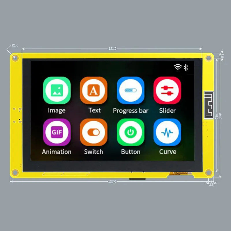
- ESP32-S3 based + SDReader + PSRAM + 4.3’ TFT (470x272) with Resistive or Capacitive touch screen
Features
Section titled “Features”- ESP32-S3 dual-core Xtensa 32-bit LX7 microprocessor, up to 240 MHz with 384KB ROM, 512KB SRAM. 2.4GHz WiFi and Bluetooth 5
- FLASH: 16MB
- PSRAM: 8MB
- Micro-SD card slot (SPI)
- 4.3-inch 480x272 TFT display - ILI9485 (Parallel RGB-565 interface)
- Touch panel options:
- ESP32-4827S043R - Resistive touch panel - XPT2046 (SPI) - not yet supported
- ESP32-4827S043C - Capacitive touch panel - GT911 (i2C - 0x5D or 0x14)
- 1 USB-C to Serial 0 (CH340C)
- I2C / SPI / GPIOs
- Boot and reset buttons
- Dimension: 181.0mm x 108.0mm
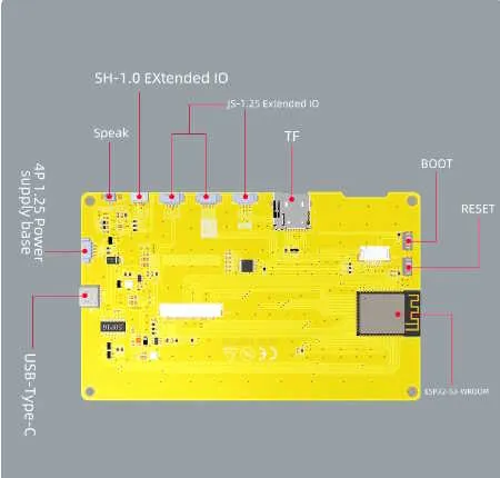
- Header P1 (4 pins) (UART): Gnd, Rx, Tx, +5V
- Header P2 (4 pins) (SPI): IO13, IO12, IO11, IO19
- Header P3 (4 pins) (USB/UART): IO20, IO19, IO18, IO17
- Header P4 (4 pins) : IO18, IO17, +3.3v, Gnd
| Pin | Usage |
|---|---|
| GPIO 0 | BOOT_BTN |
| GPIO 1 | LCD_B4 |
| GPIO 2 | TFT_BL |
| GPIO 3 | LCD_B1 |
| GPIO 4 | LCD_G5 |
| GPIO 5 | LCD_G0 |
| GPIO 6 | LCD_G1 |
| GPIO 7 | LCD_G2 |
| GPIO 8 | LCD_B0 |
| GPIO 9 | LCD_B3 |
| GPIO 10 | SD_CS |
| GPIO 11 | SD_MOSI |
| GPIO 12 | SD_SCK |
| GPIO 13 | SD_MISO |
| GPIO 14 | LCD_R4 |
| GPIO 15 | LCD_G3 |
| GPIO 16 | LCD_G4 |
| GPIO 17 | NC |
| GPIO 18 | CTP_INT* |
| GPIO 19 | CTP_SDA |
| GPIO 20 | CTP_SCL |
| GPIO 21 | LCD_R3 |
| GPIO 33 | NA |
| GPIO 34 | NA |
| GPIO 35 | NC / NA |
| GPIO 36 | NC / NA |
| GPIO 37 | NC / NA |
| GPIO 38 | CTP_RST |
| GPIO 39 | LCD_HSYNC |
| GPIO 40 | LCD_DE |
| GPIO 41 | LCD_VSYNC |
| GPIO 42 | LCD_PCLK |
| GPIO 43 | U0TXD |
| GPIO 44 | U0RXD |
| GPIO 45 | LCD_R0 |
| GPIO 46 | LCD_B2 |
| GPIO 47 | LCD_R2 |
| GPIO 48 | LCD_R1 |
* Requires Hardware Mod
Hardware Mod (Add Hardware Interrupt for GT911)
Section titled “Hardware Mod (Add Hardware Interrupt for GT911)”NOTE: This only applies to the screen with the Capacitive touch panel (ESP32_4827S043C)
By default, this board does not connect the Capacitive Touch Screen’s GT911 Interrupt pin to any GPIO pins. This means that the code has to use polling instead of hardware interrupts to determine when the screen is being touched. This results in excessive CPU utilization of greater than 80%. Making the below modifications results in a significantly reduced CPU utilization of under 10% on avg (on static screens).
Steps (see picture)
Section titled “Steps (see picture)”- Install a 0 ohm resistor or solder bridge across R17. This connects the GT911’s INT pin to GPIO18.
- (If installed) Remove (pull-up) resistor R5 (GPIO18 to 3V3). The GT911’s INT pin is not strong enough to drive GPIO18 low with this resistor installed.
- (If installed) Remove U1 (XPT2046). This is not needed for the Capacitive touch panel and may conflict with GPIO18 if left on the board.
NOTE: Remember to enable the HARDWARE_MOD_GT911_INT option in CMakeLists.txt